Controlling forward link traffic channel power

a forward link and channel power technology, applied in the field of wireless communication networks, can solve the problems of limiting the data rate at which user terminals can access data, introducing a higher bit error rate for a given signal-to-noise ratio, and introducing a higher bit error rate, so as to preserve transmit power and keep interference levels

Active Publication Date: 2003-05-01
QUALCOMM INC
View PDF7 Cites 15 Cited by
  • Summary
  • Abstract
  • Description
  • Claims
  • Application Information

AI Technical Summary

Benefits of technology

[0026] An advantage of the present invention is that it eliminates the need for closed loop forward link power control techniques where user terminals transmit commands that specify particular forward link transmit power adjustments.
[0027] Another advantage of the present invention is that it keeps interference levels within acceptable ranges, while conserving transmit power.
[0028] Further features and advantages of the present invention, as well as the structure and operation of various embodiments of the present invention, are described in detail below with reference to the accompanying drawings.
[0029] The present invention is described with reference to the accompanying drawings. In the drawings, like reference numbers indicate identical or functionally similar elements. Additionally, the left-most digit(s) of a reference number identifies the drawing in which the reference number first appears.
[0031] FIG. 2 illustrates an exemplary footprint having a plurality of beams;

Problems solved by technology

This puncturing can limit the data rates at which user terminals transmit information to gateways and base stations.
Additionally, punctured channels may not be as reliable because punctured commands may introduce a higher bit error rate for a given signal-to-noise ratio.
Since satellite and cellular communications systems employ multiple beams, transmissions received by user terminals in a particular beam are susceptible to interference from transmissions designated for neighboring beams.
Namely, the closer a user or user terminal is to an adjacent beam, the more susceptible the user is to interference from neighboring beams.
However, since user terminals can experience varying degrees of interference susceptibility, this approach has the drawback of wasting power on users that are not as susceptible to interference as others.
In addition, this approach can cause additional interference with other user terminals.

Method used


Image

  • Controlling forward link traffic channel power
  • Controlling forward link traffic channel power
  • Controlling forward link traffic channel power

Examples


Embodiment Construction

[0036] I. Exemplary Operational Environment

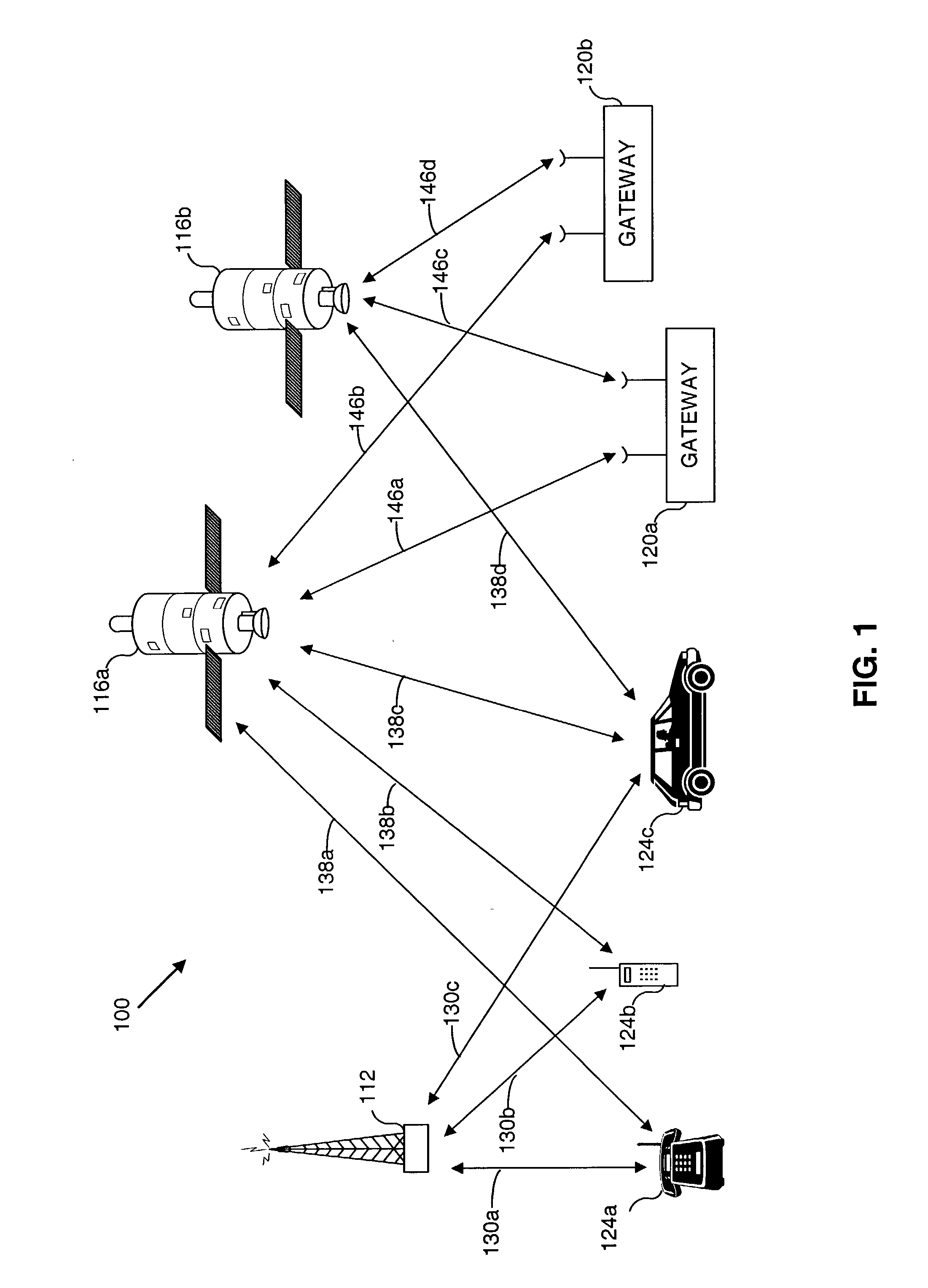
[0037] Before describing embodiments of the invention in detail, it is helpful to describe an example environment in which the invention may be implemented. The present invention is particularly useful in mobile communications environments. FIG. 1 illustrates such an environment.

[0038] FIG. 1 is a block diagram of an exemplary wireless communication system (WCS) 100 that includes a base station 112, two satellites 116a and 116b, and two associated gateways (also referred to herein as hubs) 120a and 120b. These elements engage in wireless communications with user terminals 124a, 124b, and 124c. Typically, base stations and satellites / gateways are components of distinct terrestrial and satellite based communication systems. However, these distinct systems may interoperate as an overall communications infrastructure.

[0039] Although FIG. 1 illustrates a single base station 112, two satellites 116, and two gateways 120, any number of these eleme...


PUM


Abstract

Forward link transmission power to a user terminal in a wireless communications system having a plurality of beams is controlled by determining a baseline power level, Pbaseline, from a received active pilot channel signal-to-noise ratio (SNR); determining a power margin, Pmargin, from an identified interference susceptibility; determining a power level correction, Pcorrection, based on an identified packet error rate (PER); and setting Ptransmit based on Pbaseline, Pmargin, and Pcorrection. For example, Ptransmit may be set to a power level that is substantially equal to the sum of Pbaseline, Pmargin, and Pcorrection. The determination of each of Pbaseline, Pmargin, and Pcorrection may be performed in independently running control loops or processes.

Description

[0001] This application claims priority from U.S. Provisional Patent Application entitled "System And Method For Controlling Forward Link Traffic Channel Power," Serial No. 60 / 335,749, filed Oct. 25, 2001, which application is incorporated herein by reference in its entirety.[0002] I. Field of the Invention[0003] The present invention generally relates to wireless communications networks. More particularly, the present invention relates to methods and apparatus for controlling transmission power.[0004] II. Background Art[0005] There are a variety of wireless communication systems having multiple beam communication links. A satellite-based communication system is one such example. Another example is a cellular communication system.[0006] A satellite-based communication system includes one or more satellites to relay communications signals between gateways and user terminals. Gateways provide communication links for connecting a user terminal to other user terminals or users of other ...

Claims


Application Information

Patent Timeline
Patent Type & Authority Applications(United States)
IPC IPC(8): H04B1/00H04B7/005H04B7/185H04B7/216H04B7/26H04J13/00H04W52/14H04W52/16H04W52/20H04W52/28H04W52/48
CPCH04B7/18543H04W52/143H04W52/48H04W52/20H04W52/283H04W52/16
Inventor ANDERSON, JON J.MALLADI, DURGA P.DOERFLER, STEVE J.
Owner QUALCOMM INC
Why Eureka
Try Eureka