

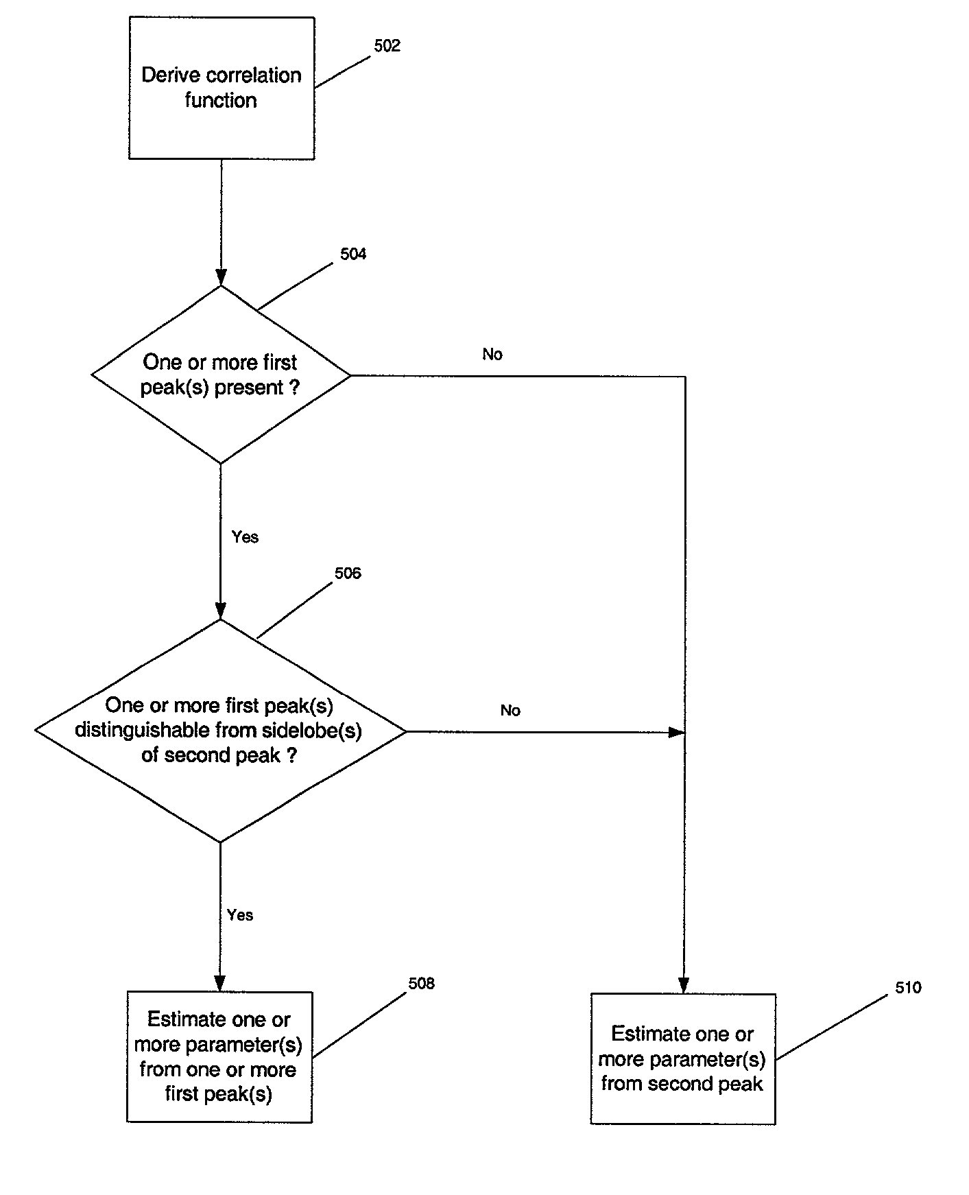
Parameter estimator configured to distinguish between peaks and sidelobes of correlation function
a correlation function and parameter estimator technology, applied in the direction of amplitude demodulation, line-fault/interference reduction, instruments, etc., can solve the problems of significant degradation of position accuracy, transmissions from base stations or sectors are subject to more severe distortions, and the detector is not generally effective for the purpose of estimating
- Summary
- Abstract
- Description
- Claims
- Application Information
AI Technical Summary
Problems solved by technology
Method used
Image

Examples
Embodiment Construction
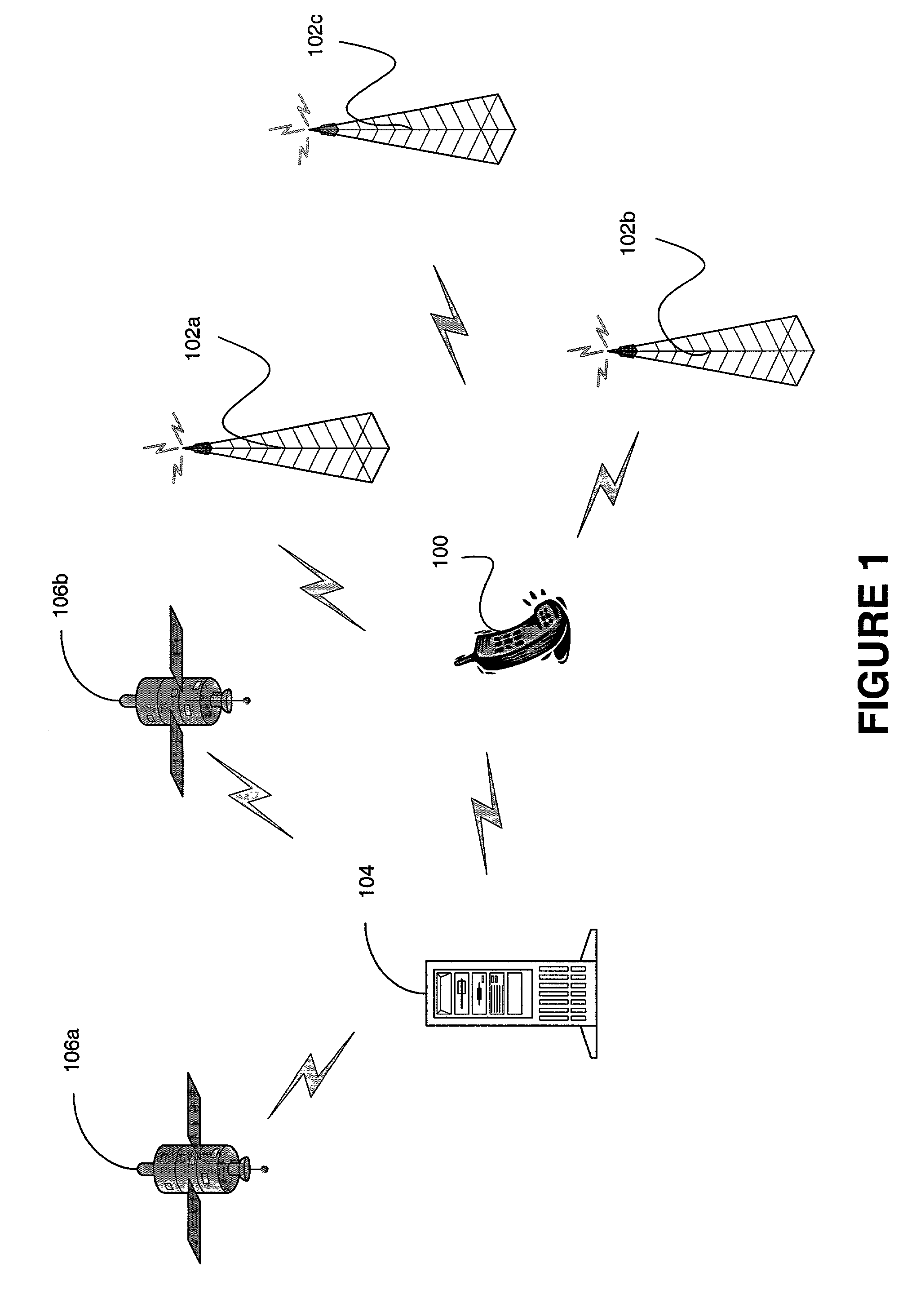
[0042] Referring to FIG. 1, an example application of a parameter estimator according to the invention is illustrated. In this example application, the parameter estimator is employed within subscriber station 100 for the purpose of estimating its location. The subscriber station 100 is a component of a wireless communication system such as but not limited to cellular, fixed wireless, PCS, and satellite communications systems. Moreover, the wireless communications system may provide for multiple access in accordance with CDMA, TDMA, FDMA, or GSM multiple access protocols, or combinations thereof.
[0043] One or more base station(s) or sector(s) 102a, 102b, and 102c are employed in the wireless communications system. Each base station or sector 102a, 102b, 102c transmits a pilot signal which is modulated with a repeating pseudo-random noise (PN) code which uniquely identifies that base station or sector. For IS-95 compliant CDMA systems, the PN code is a sequence of 32,768 chips which ...
PUM
 Abstract
Description
Claims
Application Information