Subterranean fluid cavity and methods and systems comprising same

a fluid cavity and subterranean technology, applied in the direction of sewage draining, ways, applications, etc., can solve the problems of water accumulation, soft spots or erosion of the surface of the growing medium, and the drowning of the plant(s) contained therein

Inactive Publication Date: 2003-05-01
GREEN TECH LLC
View PDF8 Cites 37 Cited by
  • Summary
  • Abstract
  • Description
  • Claims
  • Application Information

AI Technical Summary

Benefits of technology

0011] In a further embodiment, there is provided a method for directing the flow of a fluid within a medium comprising the steps of: providing a system of interconnected modules defining a pathway for the flow of the fluid wherein each module is comprised of a top with perforations, a base that is adjacent and substantially parallel to the top thereby defining an cavity for passage of fluid therein, and a plurality of supports interposed between the top and the base that maintain the height of the cavity; retaining the fluid within the plurality of modules via the perforations on the top of the modules; and directing the fluid through the pathway formed by the interconnected modules. The supports are sufficient in number, size, and physical properties as to permit the top to support the weight of the medium.

Problems solved by technology

Environmental events, such as heavy rain fall or snow fall, or man-made events, such as over-watering or fertilization, may cause damage due to the accumulation of water, fluids, and / or other waste products on the natural grass playing surface or growing surface of a lawn, turf, or garden.
These may lead to soft spots or erosion of the surface of the growing medium.
In this connection, these are safety concerns due to potential for slip and fall accidents as well as microbe or mold growth resulting from pooling water.
Additionally, excess accumulation of fluids on the growing medium may also lead to drowning of the plant(s) contained therein.
These systems, however, are not without their drawbacks.
Grading systems may not be practical for installations where a level surface is needed.
These systems, due to their many juncture points, may be prone to leakage of the pipe joints or failure of the pump to remove or redirect the fluid from the surface of the soil.
In addition, underground drainage pipe systems are limited in the amount of the fluid and flow rate that they may remove from the surface.
Pipe systems are also limited in the amount of fluid that they can transport into and out of the medium.
The varying efficiencies of fluid transport results in non-uniform fluid movement within the medium.

Method used


Image

  • Subterranean fluid cavity and methods and systems comprising same
  • Subterranean fluid cavity and methods and systems comprising same
  • Subterranean fluid cavity and methods and systems comprising same

Examples


Embodiment Construction

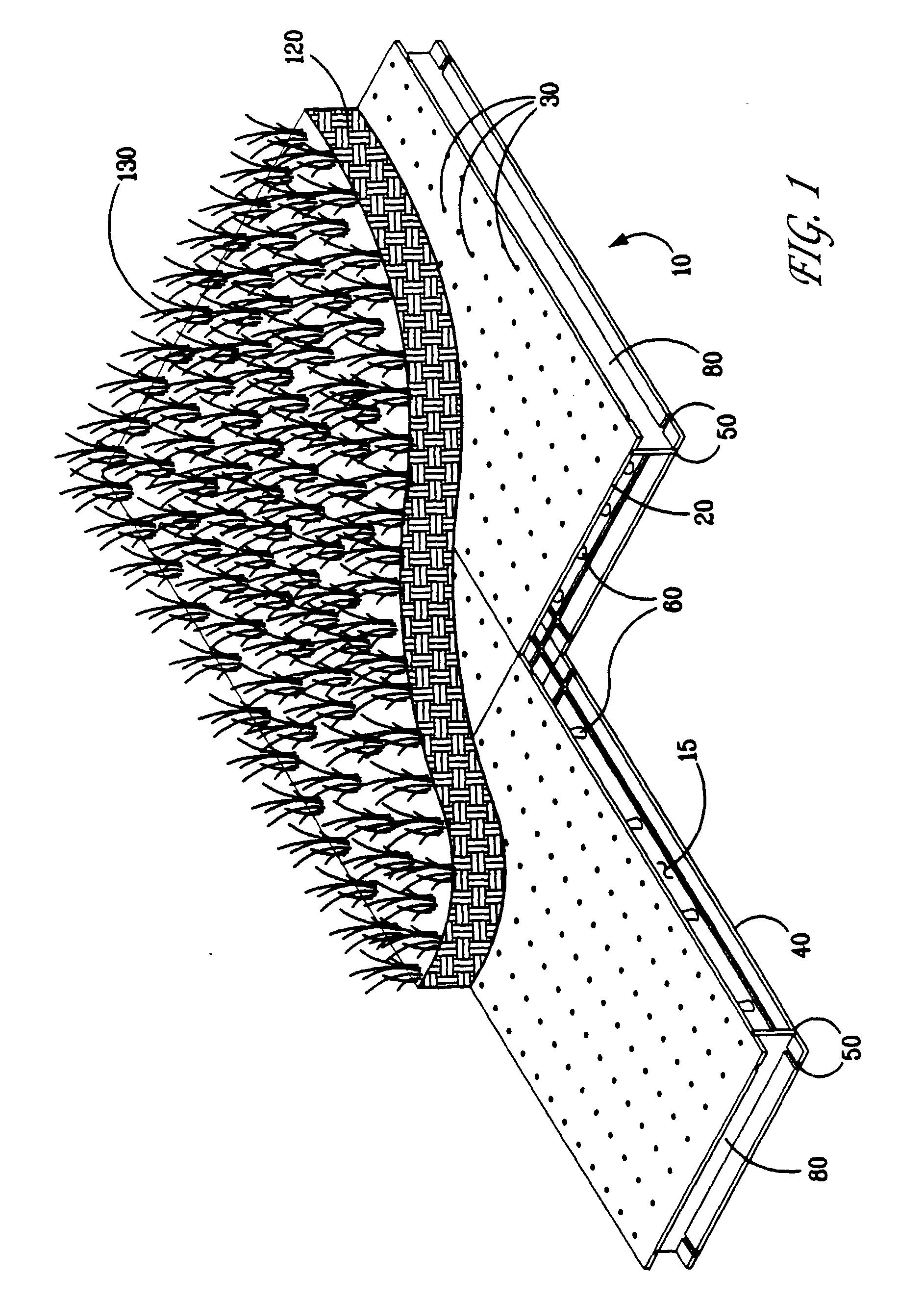
[0026] As used herein, "medium" may include of variety of substances, such as but not limited to, any naturally occurring or blended soil together with engineered plant growth materials. It may comprise sand, clay, humus, silt, individually or in combinations and may include polystyrene particles or shapes, vermiculite, and, in short, anything capable of sustaining or facilitating plant growth. The medium may also, wholly or in part, be non-plant containing. Thus, it may be or support artificial turf, e.g., Astroturf.RTM., rubberized material such as track surfaces or any other surface, especially porous or drainable surfaces. Medium may also include nutrients and minerals. Medium may further include sand or other granular substances that allow, for example, the control of storm surges and avoid taxing local storm drain systems. The medium can also be used as a filter for treating wastewater. In certain embodiments, the medium is used as a growing medium to support plants. In this c...


PUM


Abstract

The present invention is directed to, in part, modules that allow for the exchange of a fluid such as a liquid or gas to and/or from a medium or surface and systems and methods comprising same. In one embodiment, there is provided an apparatus for directing the flow of a fluid passing through a medium, the apparatus comprising a top having a plurality of perforations and a base that is positioned adjacent and substantially parallel to the top, thereby defining a cavity for passage of fluid therein. The top comprises a plurality of integrated supports extending from the bottom surface of the top, the integrated supports maintaining the height of the cavity and being sufficient in number, size, and physical properties as to permit the top to support the weight of the medium and activity above the medium. A sealing strip can be installed within the cavities of the modules to contain or direct fluid within the system.

Description

[0001] This application is a continuation-in-part of U.S. application Ser. No. 10 / 279,174 filed Oct. 24, 2002, which claims the benefit of U.S. Provisional Application No. 60 / 339,792, filed Oct. 26, 2001.FIELD OF THE INVENTION[0002] The invention relates to an integrated system of modules that control the intake and outtake of fluids, such as water or air, through a medium such soil. The apparatus of the present invention, and methods and systems comprising same, involve providing interconnected modules that reside underneath the majority of and preferably, substantially all of the medium. The modules form a subterranean cavity for fluid passage. In preferred embodiments, fluid flow can be contained and directed within the cavity.BACKGROUND OF THE INVENTION[0003] The present invention is directed to apparatuses, and systems and methods involving same, that control the subterranean environment of a variety of media, including but not limited to, artificial and natural turf surfaces i...

Claims


Application Information

Patent Timeline
Patent Type & Authority Applications(United States)
IPC IPC(8): A01G1/00E01C13/00E01C13/02E01C13/08
CPCE01C13/02E01C13/083E01C2013/006A01G1/005Y10T428/249921A01G20/20
Inventor SCOTT, CHRISTOPHER PAINE
Owner GREEN TECH LLC
Why Eureka
Try Eureka