Automatic transmission

Active Publication Date: 2003-05-01
TOYOTA JIDOSHA KK +1
View PDF3 Cites 79 Cited by
  • Summary
  • Abstract
  • Description
  • Claims
  • Application Information

AI Technical Summary

Problems solved by technology

The automatic transmission as disclosed in JP-A-2000-266138, which uses four planetary gear sets, has a relatively large axial length, and may suffer from a difficulty in installing the transmis

Method used


Image

  • Automatic transmission
  • Automatic transmission
  • Automatic transmission

Examples


first embodiment

[0110] First Embodiment

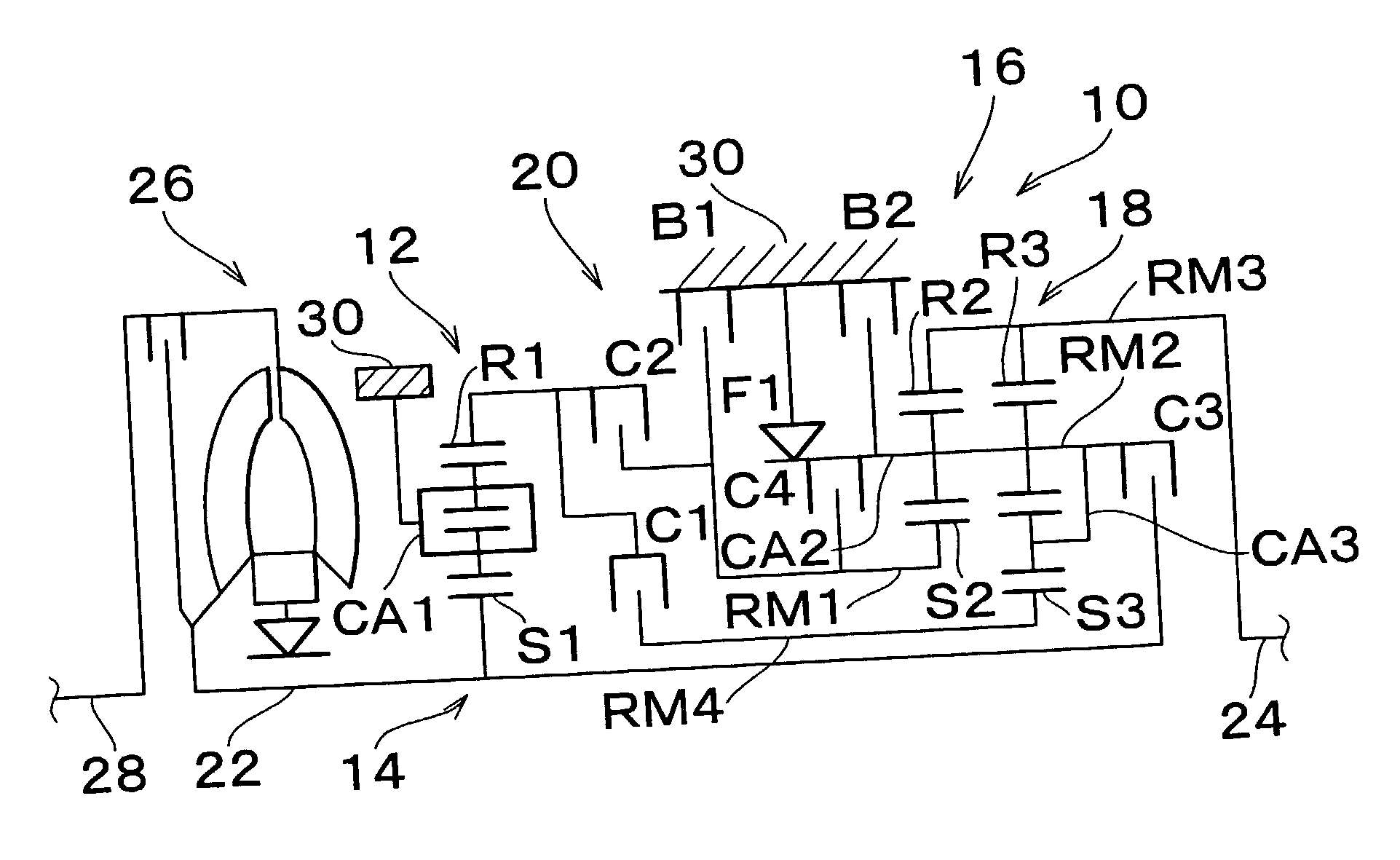
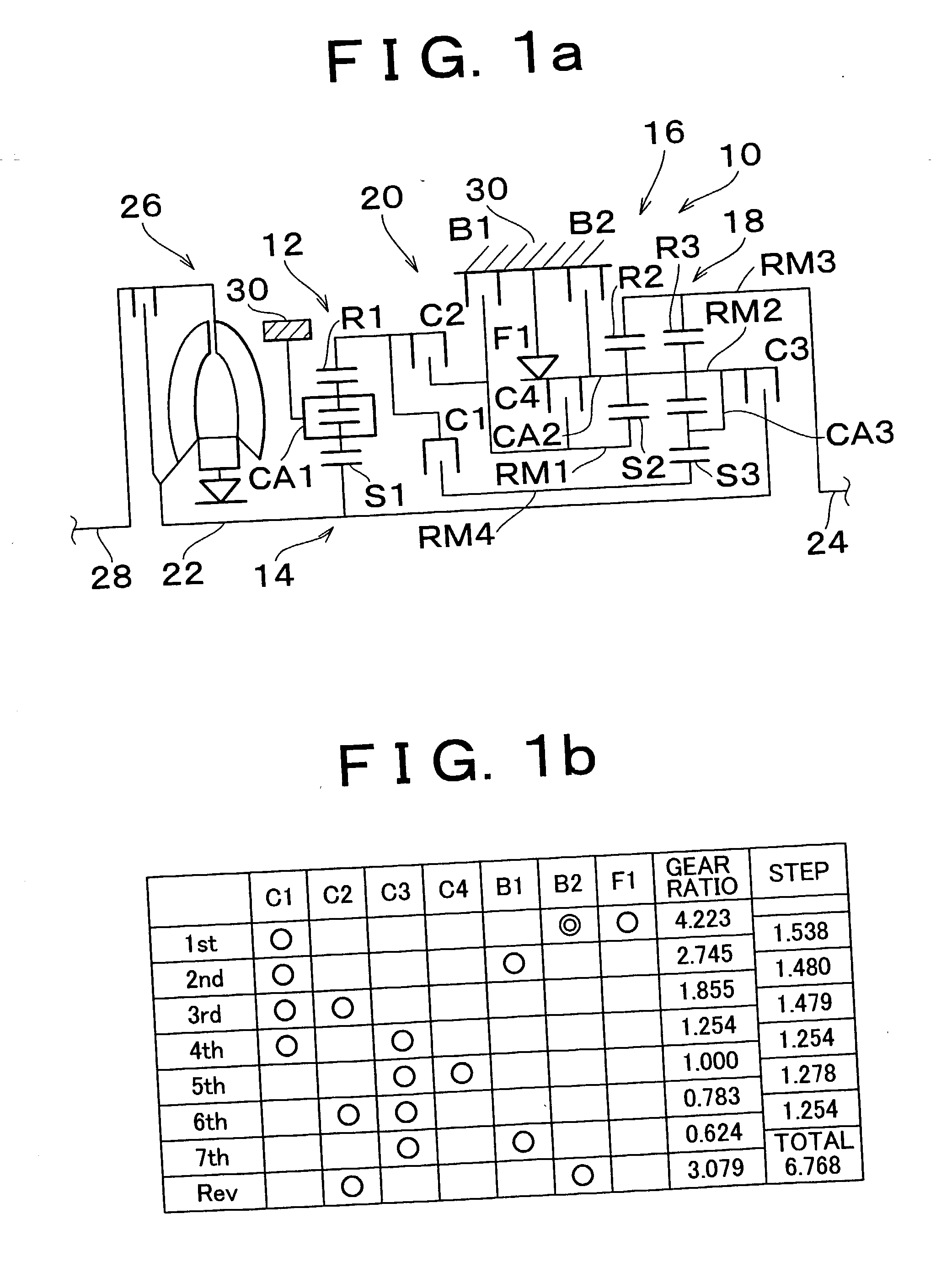
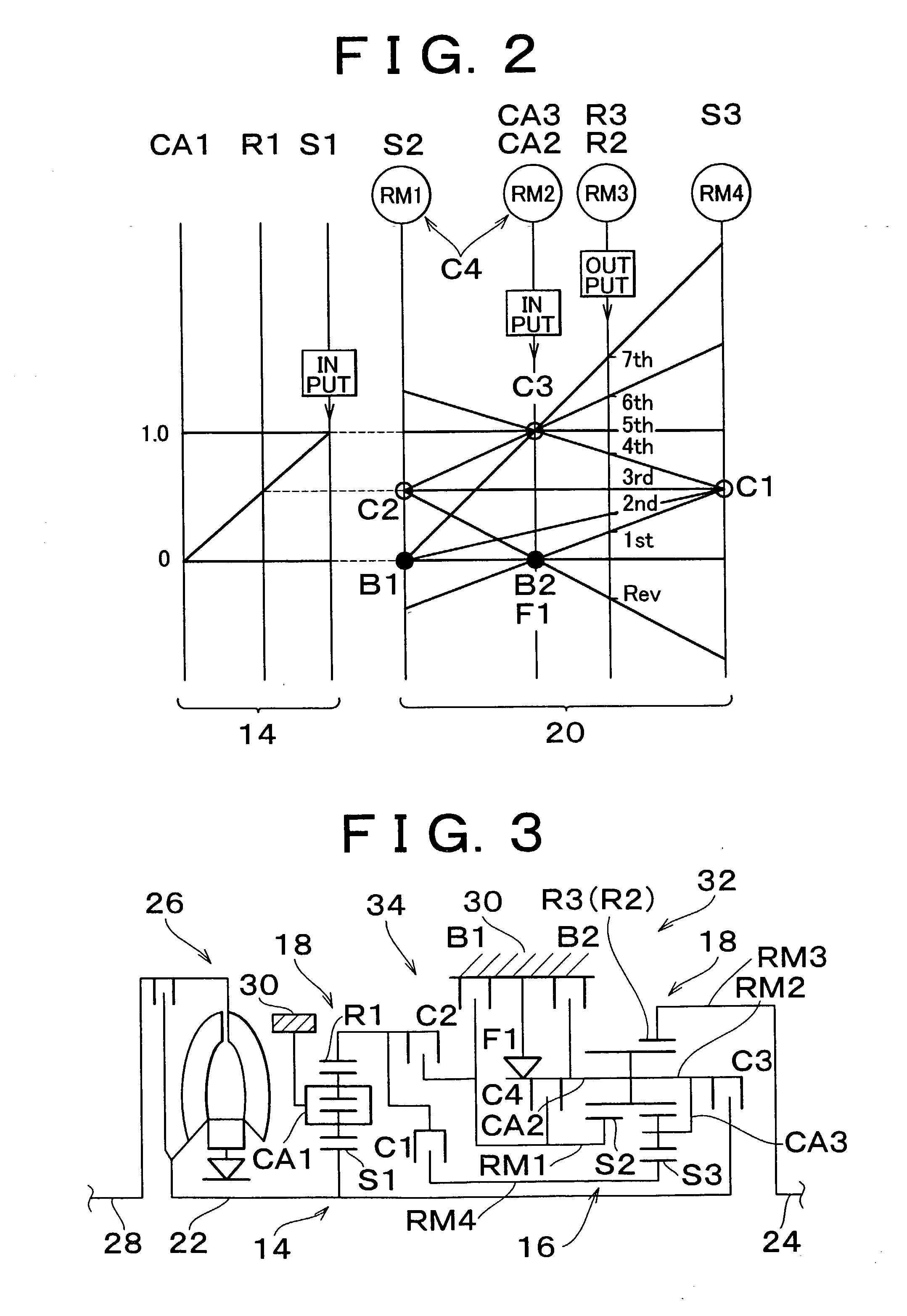
[0111] Referring to FIG. 1a, FIG. 1b and FIG. 2, the first embodiment of the invention will be described in detail.

[0112] FIG. 1a schematically shows an automatic transmission 10 of a motor vehicle according to the first embodiment of the invention, and FIG. 1b is an operation table useful for explaining the relationship between engaging elements and gear ratios when a plurality of gear stages are established. The automatic transmission 10 is mounted in the longitudinal direction in a vehicle, such as a FR vehicle, and includes a first transmitting portion 14 and a second transmitting portion 20. The first transmitting portion 14 mainly includes a double-pinion type first planetary gear set 12, and the second transmitting portion 20 mainly includes a single-pinion type second planetary gear set 16 and a double-pinion type third planetary gear set 18. The automatic transmission 10 thus constructed transmits rotary power from an input shaft 22 to an output shaft...

third embodiment

[0133] Third Embodiment

[0134] Referring next to FIGS. 6a, 6b and FIG. 7, the third embodiment of the invention will be described. FIGS. 6a and 6b correspond to FIGS. 1a and 1b, and FIG. 7 corresponds to FIG. 2. An automatic transmission 40 of a motor vehicle according to the third embodiment is different from the automatic transmission 10 of the first embodiment as shown in FIGS. 1A, 1B and FIG. 2 in respect of the construction of the second transmitting portion 42. More specifically, the sun gear S2 of the second planetary gear unit 16 and the sun gear S3 of the third planetary gear unit 18 are coupled to each other to provide the first rotating element RM1, and the carrier CA2 of the second planetary gear set 16 and the ring gear R3 of the third planetary gear set 18 are coupled to each other to provide the second rotating element RM2. The ring gear R2 of the second planetary gear set 16 provides the third rotating element RM3, and the carrier CA3 of the third planetary gear set 1...

fourth embodiment

[0136] Fourth Embodiment

[0137] Referring next to FIGS. 8a, 8b and FIG. 9, the third embodiment of the invention will be described. FIGS. 8a and 8b correspond to FIGS. 1a and 1b, and FIG. 9 corresponds to FIG. 2. An automatic transmission 44 of a motor vehicle according to the fourth embodiment is different from the automatic transmission 40 of the third embodiment as shown in FIGS. 6a, 6b and FIG. 7 in that the first transmitting portion 38 as described above with respect to the second embodiment is used in place of the first transmitting portion 14.

[0138] In this case, too, seven forward gear stages, i.e., the 1.sup.st-speed gear stage through the 7.sup.th-speed gear stage, and one reverse gear stage are established according to the operation table of FIG. 8b that is identical with that of FIG. 6b. The transmission gear ratios of the respective gear stages are suitably determined depending upon the respective gear ratios .rho.1, .rho.2 and .rho.3 of the first, second and third plan...


PUM


Abstract

An automatic transmission includes a first rotating element provided by a sun gear of a second planetary gear set, a second rotating element provided by coupling carriers of the second planetary gear set and a third planetary gear set to each other, a third rotating element provided by coupling ring gears of the second and third planetary gear sets to each other, and a fourth rotating element provided by a sun gear of the third planetary gear set. The second and third planetary gear sets are combined with a first planetary gear set so that the automatic transmission can provide seven forward gear stages by changing a combination of two engaging elements, such as clutches and brakes, for coupling or stopping the corresponding rotating elements.

Description

INCORPORATION BY REFERENCE[0001] The disclosure of Japanese Patent Applications No. 2001-332178 filed on Oct. 30, 2001 and No. 2002-067088 filed on Mar. 12, 2002, including the specification, drawings and abstract, is incorporated herein by reference in its entirety.[0002] 1. Field of the Invention[0003] The invention relates to an automatic transmission, and more particularly to an automatic transmission capable of providing seven forward gear stages or speeds by using three planetary gear sets and also capable of shifting from one gear stage to another gear stage by changing a combination of two different engaging elements, such as clutches and brakes, to be engaged.[0004] 2. Description of Related Art[0005] Automatic transmissions of motor vehicles, each including a plurality of planetary gear sets, clutches and brakes, have been widely used. Japanese Laid-Open Patent Publication No. 2000-266138 (JP-A-2000-266138) discloses an example of such an automatic transmission which is ab...

Claims


Application Information

Patent Timeline
IPC IPC(8): F16H3/66
CPCF16H3/666F16H2200/0056F16H2200/2097F16H2200/2048F16H2200/201
Inventor TABATA, ATSUSHIHOJO, YASUOHOSHINO, AKIRAMIYAZAKI, TERUFUMI
Owner TOYOTA JIDOSHA KK
Why Eureka
Try Eureka