Ball joint bearing block lubrication device

a ball joint bearing and lubrication device technology, applied in mechanical devices, couplings, transportation and packaging, etc., can solve the problems of difficult process implementation, high friction force, and inability of the hinge pin to rotate within the ball under satisfactory conditions

Inactive Publication Date: 2003-05-08
AIRBUS OPERATIONS (SAS)
View PDF4 Cites 14 Cited by
  • Summary
  • Abstract
  • Description
  • Claims
  • Application Information

AI Technical Summary

Benefits of technology

[0025] This device renews the lubricant, in other words usually grease, between the lubricated surfaces of the bearing block during each rotation of the pivot hinge pin. Therefore, depending on the capacity of the reservoir, grease is therefore used much less frequently than if a lubrication device according to prior art is used. This limits aging and consequently improves the lubrication quality.
[0027] Furthermore, since the pumping means inject grease into the grooves during each rotation of the pivot hinge pin, there is no longer any risk of poor lubrication of contact surfaces due to lack of grease, as is possible with a device according to prior art.
[0035] In one advantageous variant embodiment, the two chambers with variable volume are connected to a compensation chamber that contains lubricant kept under pressure by appropriate means, such as a second piston. This variant can reduce the dimensions or use seals with lower sealing characteristics.

Problems solved by technology

This process becomes difficult to implement when the dimensions of the ball joint are large.
These friction forces are particularly high if the loads producing the deformations are high and if the friction coefficient between the surfaces is bad.
Friction forces may also make it impossible for the hinge pin to rotate within the ball under satisfactory conditions, when a torque and / or axial forces are applied to the said hinge pin.
These phenomena can sometimes cause damage to landing gear hinge pins, for example due to occurrence of local overstresses at the ends of the bearing block, due to bending of the hinge pin that causes a longitudinal misalignment of the hinge pin in the bearing block.
This rotation causes misalignment of the lubrication orifices and lubrication grooves.
The result is that grease can no longer be replaced in the said grooves, which can have the consequence of causing damage to insufficiently lubricated surfaces, in other words damage to the ball joint.
Finally, the phenomena caused by friction forces may also cause damage to the fittings forming the structural parts of the landing gear, when torques and parasite forces have been applied to them.
These various problems are particularly sensitive when deformations of the aircraft structure are large.
This technique for the renewal of grease used to lubricate ball joint bearing blocks in aircraft landing gear introduces several problems.
Therefore, the grease ages, which is usually accompanied by a deterioration to its lubrication properties.
This degradation is worsened by pollution, temperature and pressure variations, etc.
Furthermore, if the quantity of new grease injected during a maintenance operation is insufficient, it is possible that not all old grease will be expelled from the lubricated surfaces.
In this case, lubrication of the said surfaces will not be as good because the old grease will remain mixed with new grease.
This situation is particularly likely, since old grease can sometime block up the grooves, preventing it from being entirely replaced by new grease.
Furthermore, after a number of operations of the landing gear, some of the grease is expelled on the edges of the lubricated surfaces.
Therefore, lubrication of these surfaces is not as good due to the lack of grease.

Method used


Image

  • Ball joint bearing block lubrication device
  • Ball joint bearing block lubrication device
  • Ball joint bearing block lubrication device

Examples


Embodiment Construction

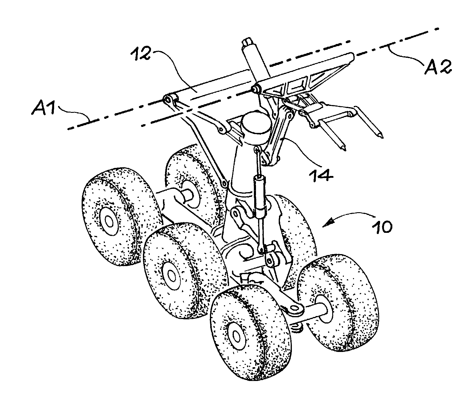
[0046] The embodiment illustrated on the figures is particularly applicable to lubrication of ball joint bearing blocks used on pivot hinge pins through which a retractable aircraft landing gear is articulated on the structure of this aircraft.

[0047] However, it will be observed that the invention is not limited to this application and that it may be used in all cases in which a pivot or rotation hinge pin is supported by a structure such that rotation movements of the said axis are sufficiently slow to enable suitable circulation of grease.

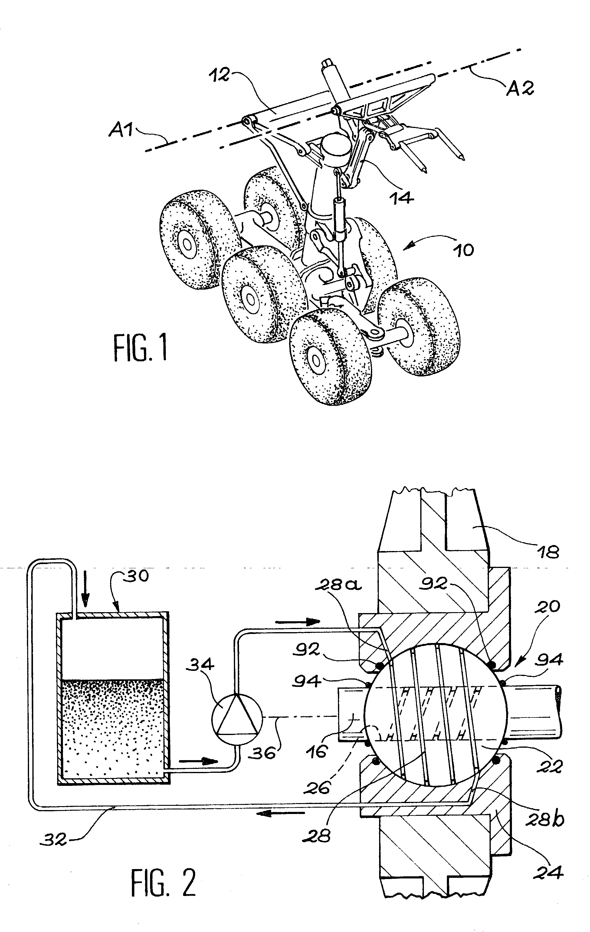
[0048] As shown diagrammatically, for example in FIG. 1, the connection between a retractable landing gear of the aircraft 10 and the structure (not shown) of this aircraft comprises a number of pivot or rotation hinge pins. In the case shown in FIG. 1, the connection comprises two pivot hinge pins, but only the center lines of these hinge pins are shown in A1 and A2.

[0049] Each of these pivot hinge pins is fixed to a part of the landing gear 10,...


PUM


Abstract

Lubrication device for a ball joint bearing block. The device comprises at least one reservoir grease (30), a pump (34) capable of circulating grease between the reservoir and at least one bearing block lubrication groove (28), and a system (36) designed to actuate the pump (34) at every rotation movement of a hinge pin (16) of the bearing block. Preferably, there is a first groove (28) between the cage (24) and the ball (22) of the ball joint, and a second groove between the ball (22) and the hinge pin (16). Each rotation of the hinge pin (16) thus alternately controls injection of grease into one of the two grooves. One preferred application is lubrication of the hinge pins of aircraft landing gear.

Description

[0001] The invention relates to a device designed for lubrication of a bearing block with a ball joint.[0002] More precisely, the invention relates to a device to automatically lubricate a ball joint in a closed circuit, during rotation movements of a hinge pin supported by the bearing block.[0003] The invention is particularly but not exclusively applicable to bearing blocks supporting landing gear on the structure of an aircraft. In this case, lubrication is done during landing gear extension and retraction movements.STATE OF THE ART[0004] An aircraft retractable landing gear comprises several parts, such as the main fitting of the landing gear and the strut, that are equipped with a number of hinge pins fixed in rotation to the aircraft structure, in order to define the same number of rotation axes (for example two axes of rotation in the transverse direction relative to the aircraft). These axes of rotation define a down and up movement for the landing gear, in the case of the a...

Claims


Application Information

Patent Timeline
Patent Type & Authority Applications(United States)
IPC IPC(8): F16C11/06F16N7/36
CPCF16C11/068F16N7/36F16C23/045Y10T403/32631Y10T403/259Y10T403/32639F16C33/102
Inventor RENIAU, GREGORY
Owner AIRBUS OPERATIONS (SAS)
Why Eureka
Try Eureka