Drum-type gear with oil supply and lubrication functions

A technology of drum-shaped teeth and gears, applied in the direction of components with teeth, gear lubrication/cooling, belts/chains/gears, etc. The effect of dynamic pressure bearing performance, enhanced capillary driving force, and simple processing technology

Active Publication Date: 2021-06-01
ANHUI UNIVERSITY OF TECHNOLOGY +1
View PDF8 Cites 0 Cited by
  • Summary
  • Abstract
  • Description
  • Claims
  • Application Information

AI Technical Summary

Problems solved by technology

[0003] At present, drum-shaped gears in metallurgical transmission equipment often use thin oil lubrication. Thin oil lubrication is to inject lubricating oil into the end face of the gear pair by means of a hydraulic pump to lubricate the gear meshing surface. Internal gear pairs (such as figure 1 As shown), the contact between the gear pairs is a point contact. Under high torque conditions, the contact area deforms. After deformation, the contact area becomes an elliptical surface contact. The gap between the elliptical contact surfaces is extremely small, and the contact stress between the contact interfaces is relatively large. Therefore, only relying on the flow of lubricating oil itself, only a small part of the external oil supply can enter the gear meshing part, while most of the oil is squeezed to the periphery of the meshing area and stored in the cavity of the gear pair, so the contact area is lubricated. The quality is poor, the temperature of the gear system rises quickly under dry friction conditions and is difficult to dissipate, and the tooth surface of the drum gear is prone to gluing and wear, which affects the lubrication quality and shortens the life of the gear
However, due to the need to frequently replace the oil storage device, it brings great inconvenience to the oiling and maintenance of the coupling
[0005] Patent CN 111692220 A discloses a high-efficiency lubricated gear coupling. This patent focuses on the problem of low lubrication efficiency of the gear pair of the existing coupling. Ring groove, and connect the groove and the meshing area through the oil hole, so that the oil can enter the meshing area smoothly
This scheme improves the meshing efficiency of the drum gear, but since the drum gear needs to be equipped with an oil storage tank, it needs to be regularly replenished with lubricating grease during work, which affects the lubrication quality and work efficiency of the drum gear coupling. oil, there may be serious consequences
[0006] In summary, in the existing oil lubrication scheme of the drum type gear coupling, although the lubricating oil supplied to the end face of the gear pair is relatively sufficient, the oil at the entrance of the meshing area of ​​the gear pair cannot enter the contact interface, which can effectively lubricate the oil. The amount is seriously insufficient, and the tooth surface of the drum gear is prone to gluing wear
However, the existing structure of providing lubricating oil to the meshing area is complex and the cost increases

Method used


Image

  • Drum-type gear with oil supply and lubrication functions
  • Drum-type gear with oil supply and lubrication functions
  • Drum-type gear with oil supply and lubrication functions

Examples


Embodiment 1

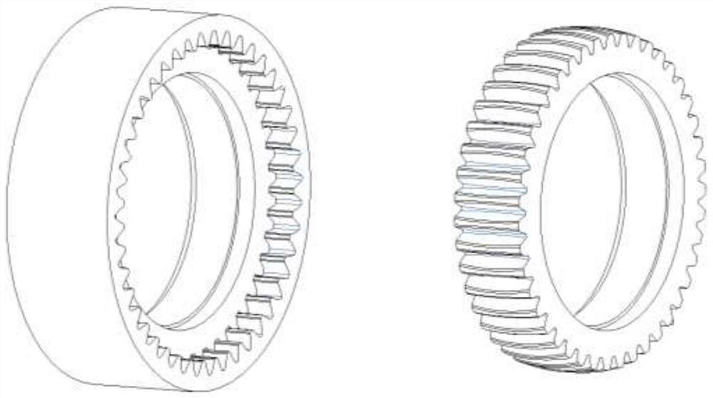
[0027] From figure 2 It can be seen that a drum gear with an oil supply lubrication function in the present invention includes a gear base 1, drum teeth 2, microporous grooves 3, shaft holes 4, and keyway holes 5; drum teeth 2 and gear base 1 are one On the whole, the micro-hole groove 3 is opened on the tooth surface of the drum-shaped tooth 2 , the shaft hole 4 is opened at the center of the gear base 1 , and the keyway hole 5 is opened on the inner wall of the shaft hole 4 .

[0028] Wherein, the shaft hole 4 is used for installing the transmission shaft, and the keyway hole 5 is used for positioning between the gear and the transmission shaft. The tooth end surface of the drum-shaped tooth 2 is an involute tooth profile, and the tooth axially bulges outward from the middle position.

[0029] The microporous groove 3 has a drainage function, that is, during the start-up stage and working process of the drum gear, the oil supply on the end surface of the external gear can ...

Embodiment 2

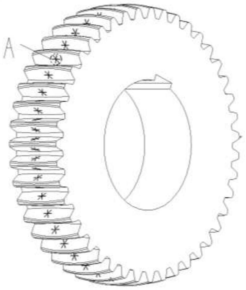
[0031] From image 3 It can be seen that the drum gear with oil supply and lubrication function of the present invention: the microporous grooves 3 are evenly opened on the contact area of ​​the front and rear two tooth surfaces of each tooth of the drum gear 2, and the number of microporous grooves 3 on each tooth surface 6 to 12.

[0032] The microporous grooves 3 are provided on both sides of the tooth surface contact area of ​​the drum gear, and the tooth surface contact area of ​​the drum gear refers to the part where the middle part of the tooth surface of the drum gear 2 bulges outward. With the development of metallurgical machinery and equipment towards high speed and heavy load, the contact stress between the contact interfaces of drum gears is relatively large, and the contact interfaces must be fully lubricated. Therefore, the microporous grooves on the single side of each tooth of the drum gear 2 The number of three is 6 to 12, thus ensuring the lubricating effec...

Embodiment 3

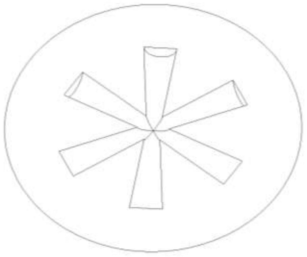
[0034] From image 3 It can be seen that the present invention has a drum gear with oil supply lubrication function: the microporous grooves 3 are distributed in a circular array on the contact area of ​​the tooth surface, and each microporous groove transitions from the outer edge to the center in a tapered shape from large to small.

[0035] The tapered shape of the microporous groove 3 from large to small further improves the capillary driving force and forms a wedge-shaped converging space. The circular array distribution of microporous grooves 3 and the conical structure make the lubricating oil flow from both ends of the gear to the center, so that the oil reaches the contact area, and at the same time form a wedge-shaped convergence space, which enhances the dynamic pressure bearing capacity of the lubricating oil film and improves the lubrication quality. The oil flow condition between the contact interfaces of the gear pairs is improved, the heat in the meshing area i...


PUM

PropertyMeasurementUnit
Axial lengthaaaaaaaaaa
Depthaaaaaaaaaa
Axial lengthaaaaaaaaaa

Abstract

The invention discloses a drum-type gear with oil supply and lubrication functions. The drum-type gear comprises a gear base body, drum-type teeth, micropore grooves, a shaft hole and key groove holes, wherein the drum-type teeth and the gear base body are integrated, the micropore grooves are formed in the tooth faces of the drum-type teeth, the shaft hole is formed in the center position of the gear base body, the key groove hole is formed in the inner wall of the shaft hole, the micropore grooves are evenly formed in the contact area of the front tooth face and the rear tooth face of each tooth of the drum-type teeth, the number of the micropore grooves in each tooth face is 6-12, the micropore grooves are distributed in the tooth surface contact areas in an annular array mode, and each micropore groove is in conical transition from large to small from the outer edge to the center. According to the drum-type gear, lubricating oil on the end face of a gear pair can permeate into a contact interface, circulating flow of a lubricating agent is formed between the contact interfaces, efficient lubrication of the drum-type gear is guaranteed, and the working requirement of continuous casting and rolling metallurgy transmission equipment is met.

Description

technical field [0001] The invention relates to the technical field of lubrication of drum gear couplings in rolling machines, in particular to the drum gear lubrication technology in drum gear couplings. Background technique [0002] Continuous casting and rolling (CSP) of thin plate and strip is a cutting-edge technology in the metallurgical industry. It has the advantages of reliable rolling precision, high efficiency, and low energy consumption. The stability of CSP rolling process puts forward higher performance requirements for its transmission equipment. Since the tooth end face of the drum gear is an involute tooth profile, and the middle position of the gear tooth bulges outwards in the axial direction, when the drum gear meshes with the inner ring gear to transmit power, there may be a gap between the inner ring gear and the drum gear. Small angular displacement and axial displacement, so that the two connecting shafts of the drum gear coupling have a certain self-...

Claims


Application Information

Patent Timeline
IPC IPC(8): F16H55/17F16H57/04
CPCF16H55/17F16H57/0431Y02T10/86
Inventor 张国涛王孝义史英康夏清华杨晓红黄显贵杨远航
Owner ANHUI UNIVERSITY OF TECHNOLOGY
Why Eureka
Try Eureka