Valve device with check valve, used for washer nozzle and hose joint

a valve device and check valve technology, applied in the direction of functional valve types, couplings, vehicles, etc., can solve the problems of difficult disassembly, difficult to be removed, and inability to maintain and repair the check valv

Inactive Publication Date: 2003-05-15
ASMO CO LTD
View PDF5 Cites 67 Cited by
  • Summary
  • Abstract
  • Description
  • Claims
  • Application Information

AI Technical Summary

Problems solved by technology

However, after the washer nozzle or the hose joint is formed, it is difficult to be disassembled, and the check valve cannot be maintained and repaired.
For example, when foreign matters are clogged in the washer nozzle or the hose joint, it is difficult to be removed.
Because a part of components constructing the washer nozz

Method used


Image

  • Valve device with check valve, used for washer nozzle and hose joint
  • Valve device with check valve, used for washer nozzle and hose joint
  • Valve device with check valve, used for washer nozzle and hose joint

Examples


first embodiment

[0022] First Embodiment

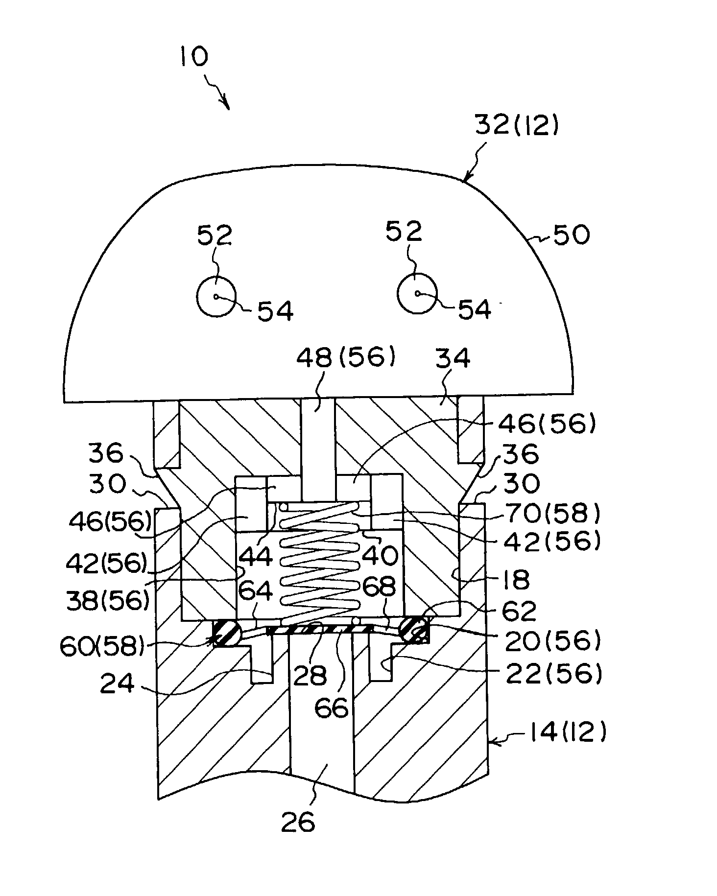
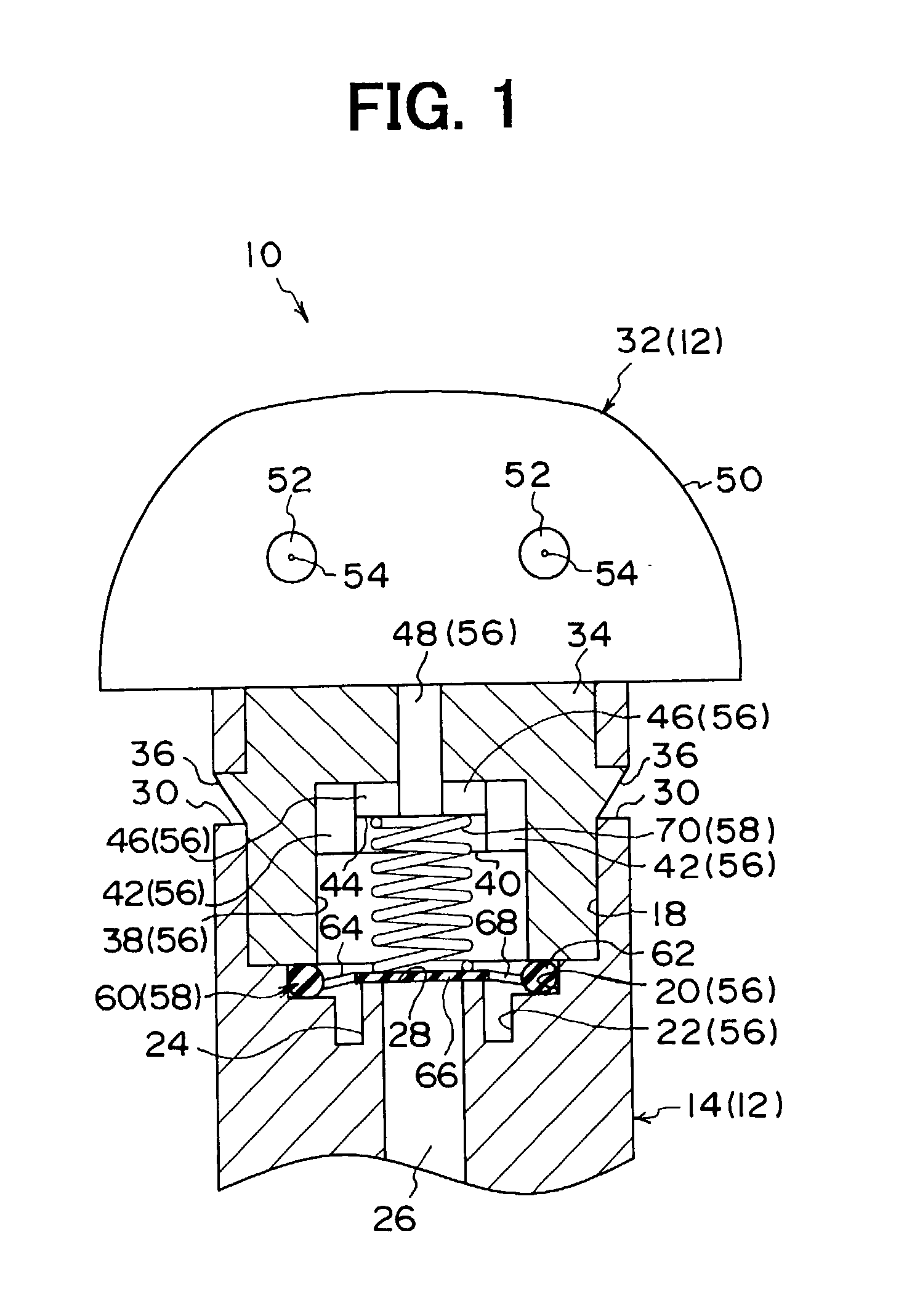
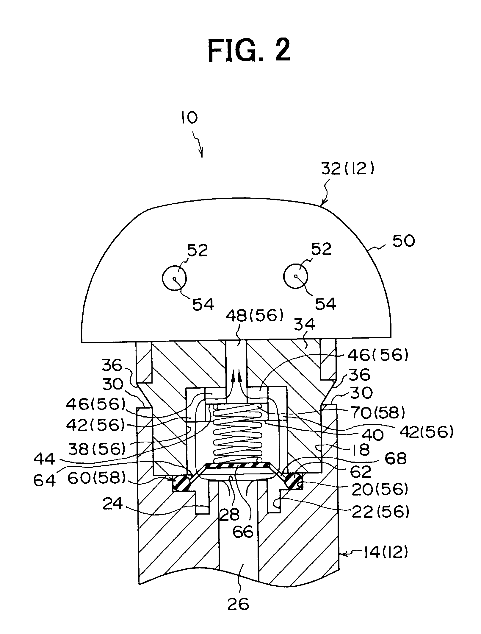
[0023] In the first embodiment, a valve device of the present invention is typically used for a washer nozzle with a check valve.

[0024] As shown in FIGS. 1-3, a washer nozzle 10 with a check valve (washer valve) 58 according to the first embodiment includes a nozzle body 12. The nozzle body 12 is disposed on a vehicle body near a windshield (not shown) such as a bonnet. The nozzle body 12 includes an approximate cylindrical lower body portion 14 at a lower side portion, and the lower body portion 14 includes a supply pipe 16 at a lower side portion. The supply pipe 16 is connected to a washer pump (not shown), attached to a washer tank (not shown) disposed in an engine compartment and the like, through a hose piping. A cleaning liquid (liquid fluid) is contained in the washer tank, and is press-sent into the lower body portion 14 through the hose piping and the supply pipe 16.

[0025] A joint hole 18 having an approximate cylindrical shape is formed in the lower...

second embodiment

[0038] Second Embodiment

[0039] In the second embodiment, the present invention is typically applied to a hose joint with the check valve.

[0040] As shown in FIGS. 6 and 7, a hose joint 200 with a check valve 244 includes a joint body 202, and the joint body 202 includes a supply body portion 204 and a discharge body portion 206. Each of the supply body portion 204 and the discharge body portion 206 is formed into an approximate cylindrical shape. In the second embodiment, the hose joint 200 is typically used for a windshield washing unit 250 shown in FIG. 8. As shown in FIG. 8, one end of the supply body portion 204 is connected to one end of a supply hose 208, and the other end of the supply hose 208 is connected to a washer pump 212 attached to a washer tank 210 disposed in the engine compartment or the like. A cleaning liquid 214 (liquid fluid) is filled in the washer tank 210, and is press-sent by operation of the washer pump 212 from the washer tank 210 to the supply body portio...


PUM


Abstract

A valve device with a check valve can be used for a washer nozzle and a hose joint. In the valve device, first and second body portions are detachably attached to each other by an attachment of a joint portion to a joint hole and by an engagement of engagement protrusions with engagement holes. A circular fixing portion of the check valve is clamped between the first and second body portions, thereby sealing an attachment portion between the first and second body portions. Further, the check valve includes plural connection portions connected to the fixing portion at a radial inside to be elastically deformed, and a valve body connected to the connection portions to open and close a supply port of the first body portion. Accordingly, the valve device has a simple structure, and it is possible to perform a maintenance in the valve device.

Description

[0001] This application is related to and claims priority from Japanese Patent Applications No. 2001-348330 filed on Nov. 14, 2001 and No. 2002-239569 filed on Aug. 20, 2002, the contents of which are hereby incorporated by reference.[0002] 1. Field of the Invention[0003] The present invention relates to a valve device with a check valve for preventing a reverse flow of a liquid fluid. The valve device can be suitably used for a washer nozzle for jetting a cleaning liquid, and a hose joint for joining a supply hose and a discharge hose.[0004] 2. Description of Related Art[0005] Generally, a washer nozzle for washing a windshield includes a check valve for preventing a reverse flow of a cleaning liquid, or a hose joint used for a cleaning liquid supply includes the check valve for preventing the reverse flow of the cleaning liquid. The washer nozzle with the check valve or the hose joint with the check valve is formed by ultrasonic welding and the like for ensuring seal performance o...

Claims


Application Information

Patent Timeline
IPC IPC(8): B05B1/10B05B15/00B60S1/52F16K15/14F16L37/08
CPCF16K15/144B60S1/52B60S1/48F16K15/1402F16K15/1441
Inventor MORIMOTO, HIROTAKA
Owner ASMO CO LTD
Why Eureka
Try Eureka