Metal tube and its production method

Inactive Publication Date: 2003-05-15
TERUMO KK
View PDF9 Cites 15 Cited by
  • Summary
  • Abstract
  • Description
  • Claims
  • Application Information

AI Technical Summary

Problems solved by technology

However, when the diameter of the tube 1 becomes reduced after repeated drawings, insertion of the plug 3 in the tube 1 becomes impossible, and such drawing with no plug 3 is inevitable.
Increase in the surface rough

Method used


Image

  • Metal tube and its production method
  • Metal tube and its production method
  • Metal tube and its production method

Examples


Example

Example 1

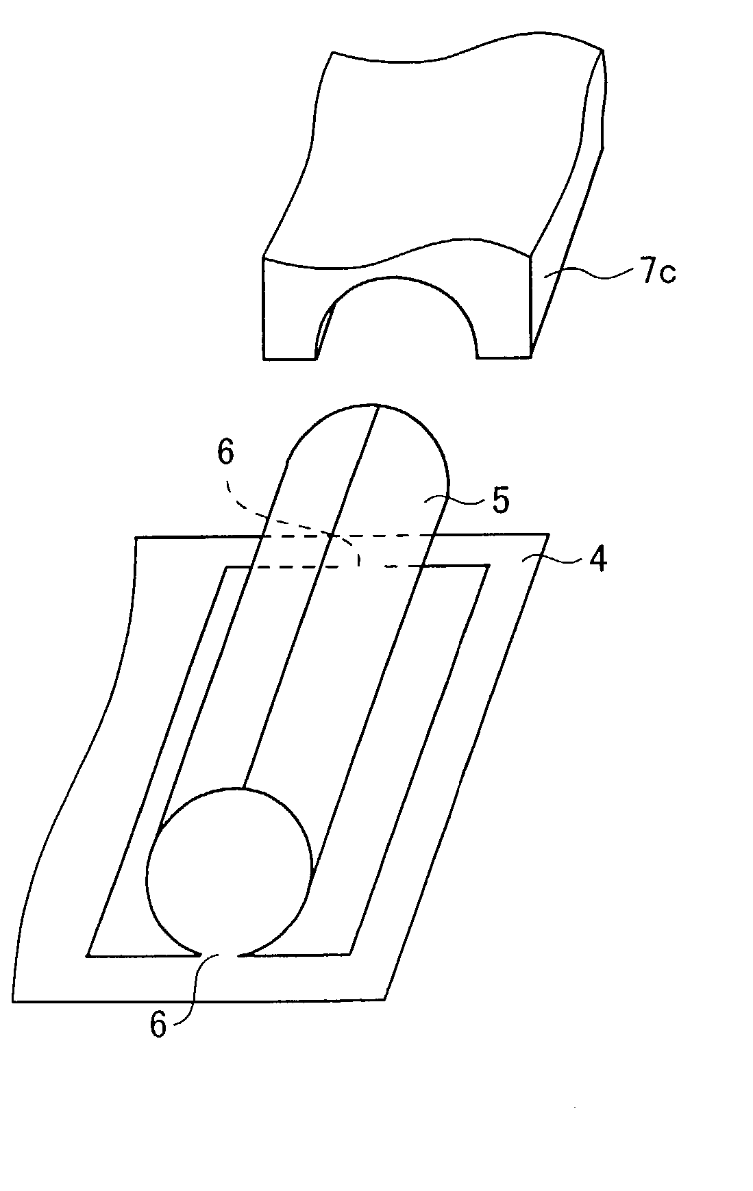
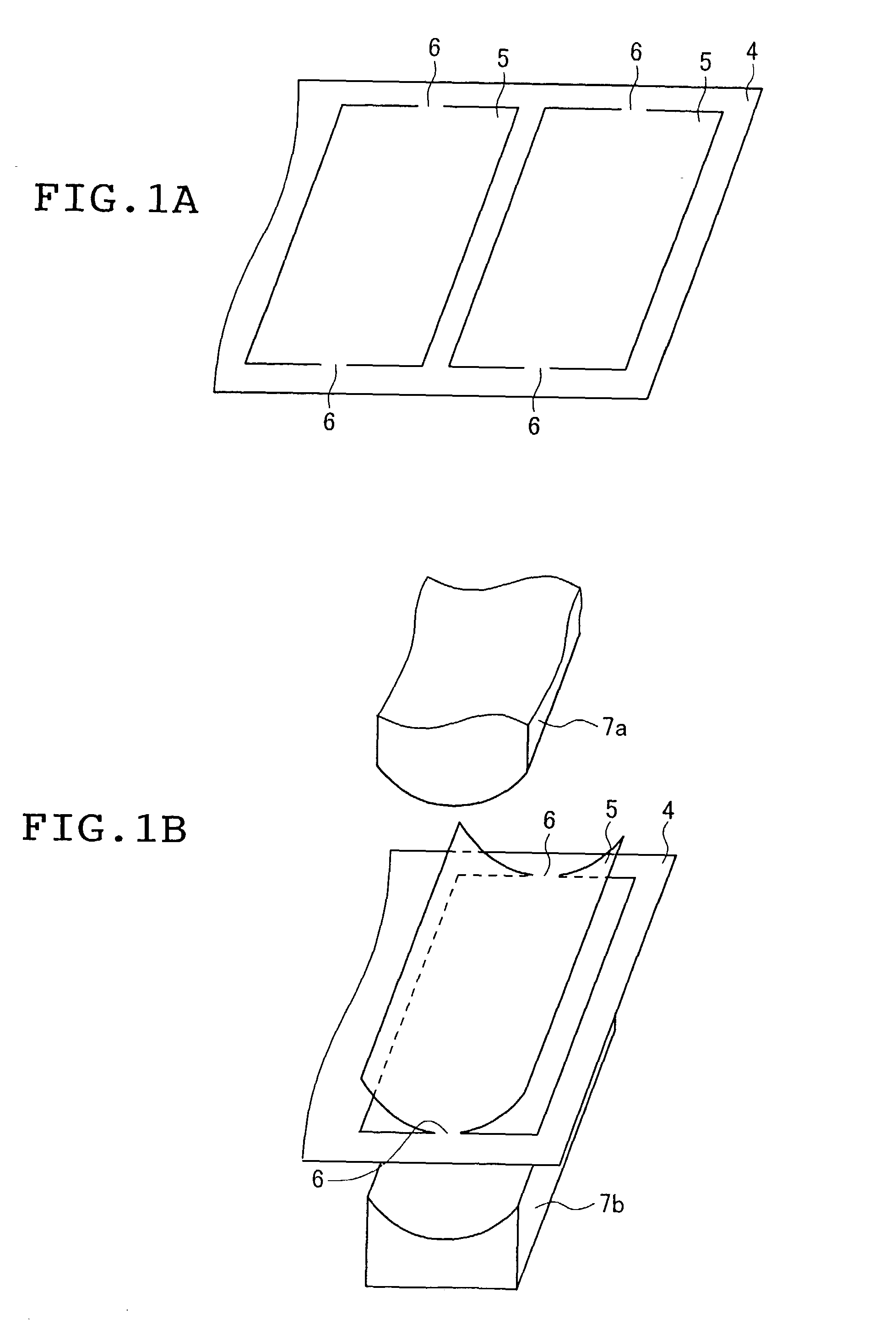
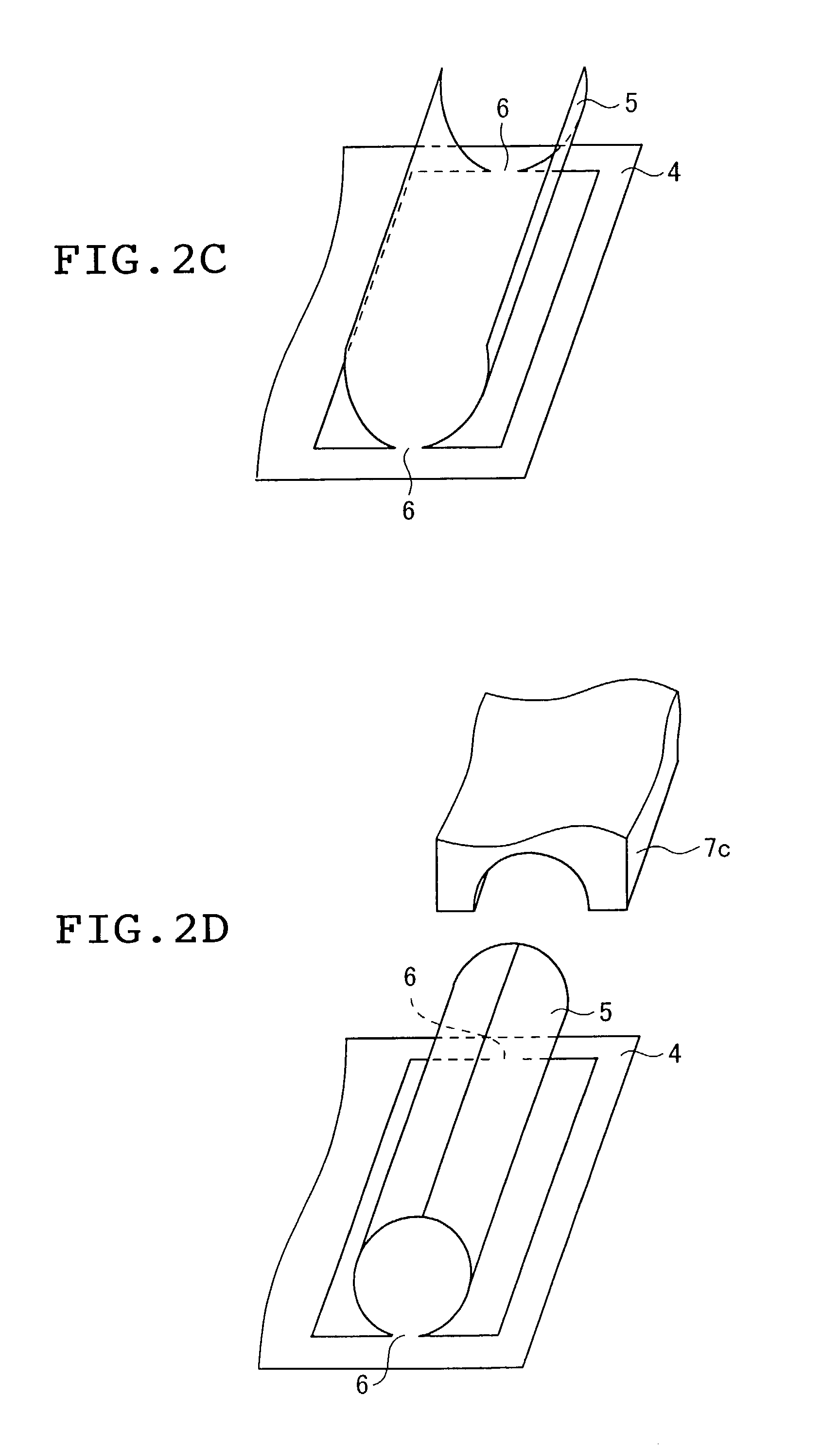
[0037] Tubes (tube 1, 2) each having an outer diameter of 0.35 mm, an inner diameter of 0.25 mm and a length of 18 mm were produced by press forming a thin plate of stainless steel (SUS304) having a thickness of 0.05 mm according to the procedure shown in FIGS. 1A, 1B, 2C and 2D. The tubes were cut parallel with the axial direction and the surface roughness of the inner surface was measured according to JIS B0601 by using a scanning type laser microscope 1LM21 (Laser Tec. Co., Ltd.) to determine the maximum height difference (Rf=R.sub.max). Rf measurements were shown in Table 1. In order to confirm the state on the inner surface of a cut tube, a micrograph was taken using 1LM21. FIG. 4B shows a micrograph of the inner surface of the tube in Example 1.

Comparative Example

[0038] A thin plate (SUS304) having a thickness of 0.17 mm was subjected to a conventional method utilizing a drawing process to thereby produce tubes (tube 1, 2) whose material and dimensions are the same as...

Example

1 TABLE 1 Comparative Example 1 Example Outer diameter 0.35 0.35 (mm) Inner diameter 0.25 0.25 (mm) Length (mm) 18 18 R.sub.max (.mu.m) 0.86 5.92 tube 1 tube 2 0.58 8.75

[0039] As is clear from Table 1, it can be confirmed in the tubes produced by the method of the present invention that their inner surfaces have each a smaller Rf and are kept smooth as compared with the tubes in Comparative Example produced by the conventional method.

[0040] Although the metal tube of the present invention has a small diameter, the inner surface thereof is kept smooth, and the resistance of a fluid passing through the tube is low. Dirt and foreign matters are less prone to adhere thereto. Therefore, the metal tube of the present invention can be suitably used in various applications requiring small diameter tubes, for example by forming into an injection needle.

[0041] In the metal tube production method according to the present invention, press forming is only necessary to obtain a tube having desire...


PUM

PropertyMeasurementUnit
Diameteraaaaaaaaaa
Diameteraaaaaaaaaa
Surface roughnessaaaaaaaaaa

Abstract

A small diameter metal tube whose inner surface is smooth and its production method are provided. The metal tube has an inner diameter of up to 1.0 mm and its inner surface has a maximum height difference (Rf) in the surface roughness of up to 3 mum.

Description

[0001] 1. Field of the Invention[0002] This invention relates to a metal tube and its production method. To be more specific, this invention relates to a small diameter metal tube whose inner surface is smooth and which can be used for a pin, injection needle, connector, electron gun for TV liquid crystal, and the like and its production method.[0003] 2. Prior Art[0004] Metal tubes of small diameter such as those having, for example, an outer diameter of up to 1.3 mm and used for a medical pin, injection needle, connector, electron gun for TV, or the like are typically produced by curling a metal thin plate having a thickness of up to 0.2 mm simultaneously with the drawing, welding the abutting edges of the thin plate just before its entrance into a drawing die, drawing the welded member through the drawing die to form a tube having an outer diameter of about 4 to 6 mm, and repeating the drawing process to thereby produce a tube product having a desired outer diameter. FIG. 3 shows ...

Claims


Application Information

Patent Timeline
IPC IPC(8): A61M25/00B21C37/06F16L9/02B21C37/08B21C37/083B21D5/01B21D51/18B21G1/08
CPCB21C37/06B21C37/0815B21C37/083Y10T29/49995Y10T29/5185Y10T428/12389Y10T428/12292Y10S138/11B21G1/08
Inventor OOYAUCHI, TETSUYAOKANO, MASAYUKI
Owner TERUMO KK
Why Eureka
Try Eureka