

Method and device for controlling the drive unit of a vehicle
a technology for driving units and vehicles, applied in the direction of electric control, ignition automatic control, speed sensing governors, etc., can solve the problem of limited flexibility in the selection of control parameters
- Summary
- Abstract
- Description
- Claims
- Application Information
AI Technical Summary
Benefits of technology
Problems solved by technology
Method used
Image

Examples
Embodiment Construction
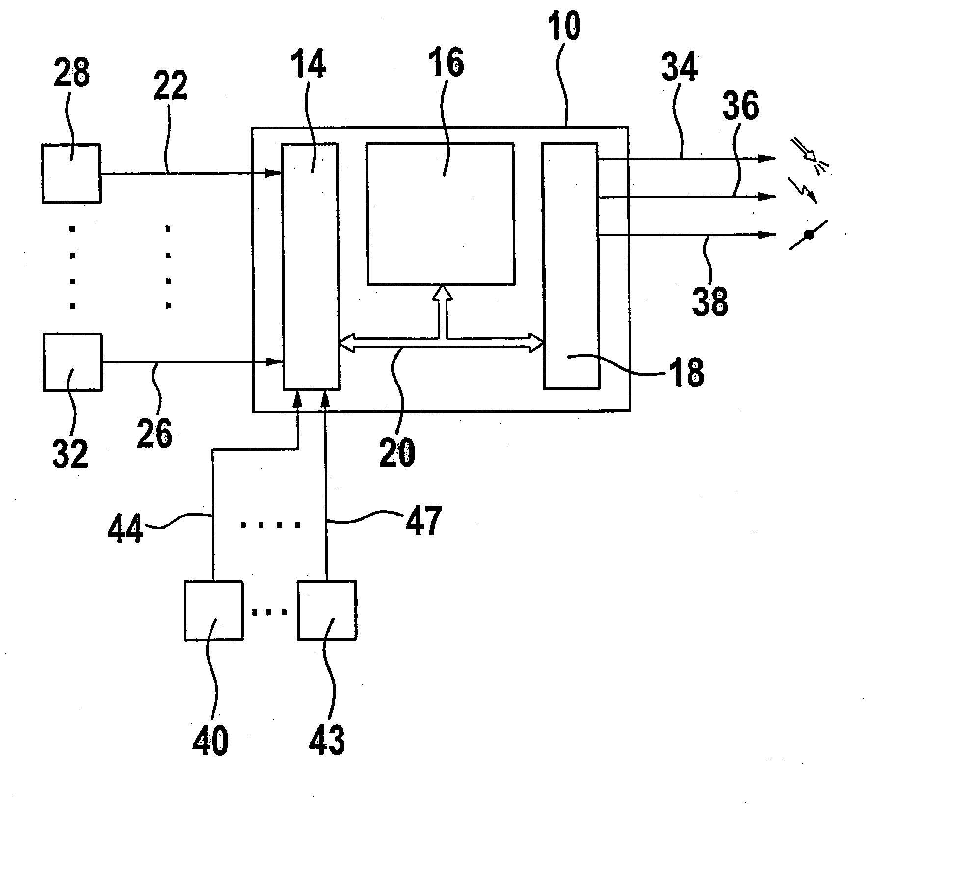
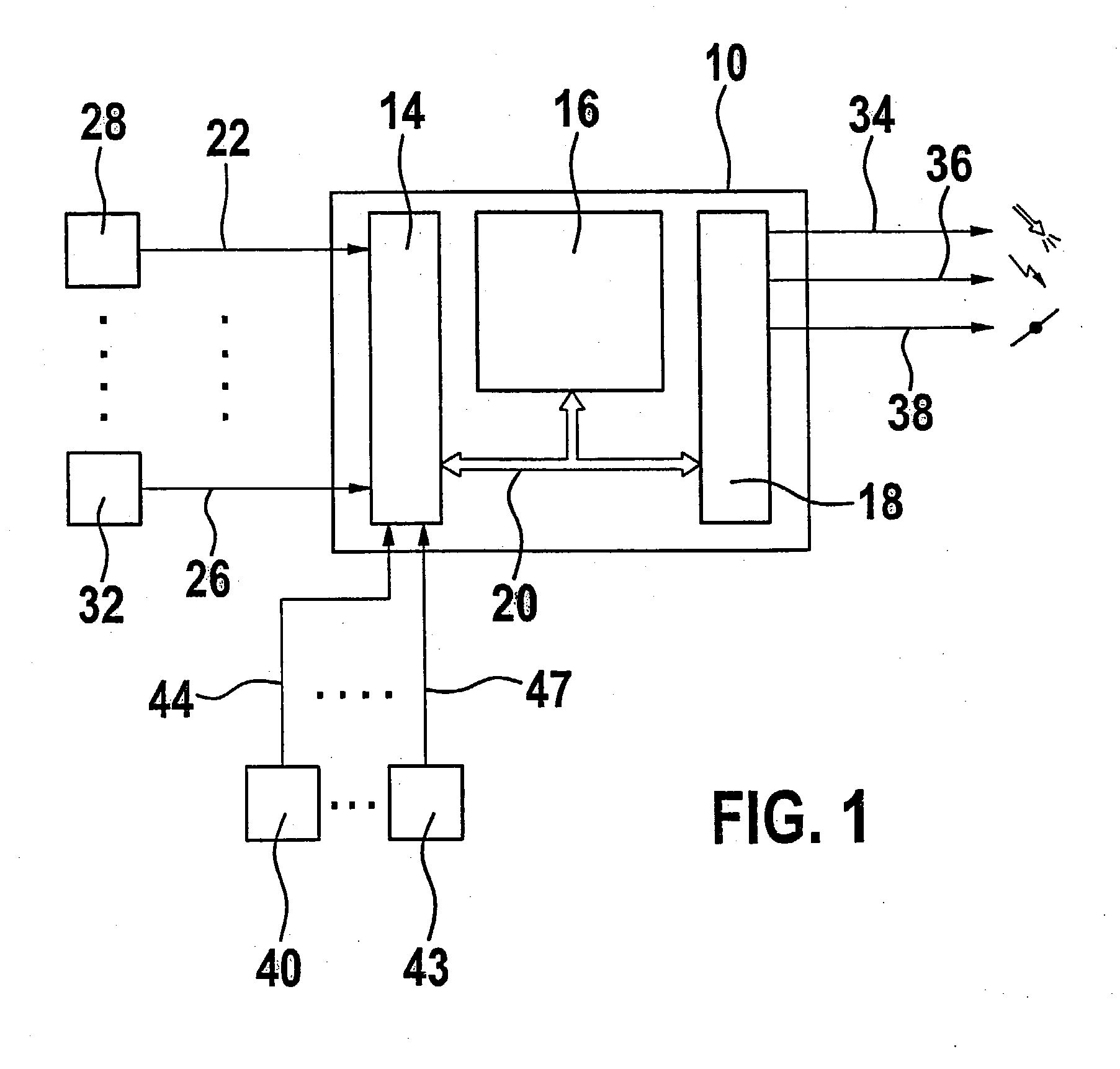
[0011] FIG. 1 shows a block diagram of a control device for controlling a drive unit, of an internal combustion engine in particular. A control unit 10 is provided, having as components an input circuit 14, at least one computer unit 16 and an output circuit 18. A communications system 20 connects these components for mutual data exchange. Input lines 22 through 26 lead to input circuit 14 of control unit 10; in a preferred embodiment, these input lines are designed as a bus system and carry signals, which represent operating variables to be analyzed for controlling the drive unit, to control unit 10. These signals are detected by measuring devices 28 through 32. Such operating variables include the accelerator pedal position, engine speed, engine load, exhaust gas composition, engine temperature, etc. Control unit 10 controls the power of the drive unit via output circuit 18. This is symbolized in FIG. 1 by output lines 34, 36 and 38 over which the fuel mass to be injected, the fir...
PUM
 Abstract
Description
Claims
Application Information