Modulator for gas chromatography

a module and gas chromatography technology, applied in the field of modules for gas chromatography, can solve the problems of easy breakage of the column, limited oven maximum temperature, and insufficient robustness for long use, and achieve the effect of optimizing the analytes treatmen

Inactive Publication Date: 2003-05-29
THERMO ELECTON
View PDF1 Cites 20 Cited by
  • Summary
  • Abstract
  • Description
  • Claims
  • Application Information

AI Technical Summary

Problems solved by technology

This system appeared not to be robust enough for long use and introduced limitations in the lower temperature of the oven housing of the two columns (as the minimum temperature of the oven should be in this case at least 100.degree. C. higher than the temperature of the modulator which is kept close to the ambient one).
However, this system too shows drawbacks, mainly due to the movement of the slotted heater in the close vicinity of the tiny capillary, which causes an easy breakage of the column and a limit of the oven maximum temperature.
The major drawback of this system is the very frequent breakage of the portion of the fused silica capillary column where the cold trap is moving due to ice formation between the cold trap and the column.
The maximum temperature of the column oven will be therefore limited to 100 C below the sweeper temperature and this introduces strong limitations in the application range covered by such systems.
The common characteristic of the thermal modulators as they have been described, however, is the fact that both techniques use a heating / cooling device that moves across a close distance around a fragile fused silica capillary column.
Even very accurate (and rather tedious) tuning of these moving devices and their short distance to the capillaries, frequently leads to breakage of the tiny, and fragile capillaries.
However, this system and the cryogenic system as previously illustrated show all drawbacks of the modulators having movable parts within the oven and moreover the continuous jet of CO.sub.2 tends to create ice formations on the column which involves, breaking possibilities and hindering of fraction release.
Liquid nitrogen is not easily available at every laboratory and needs bulky insulation when transported through tubes.
Moreover, the use of liquid nitrogen may create problems due to ice formation within the oven and in particular on the jet nozzles which may such hinder or even stop the release of liquid nitrogen.
Moreover, since the hot air jet must have a temperature at least 100.degree. C. above the oven temperature and very high air jet temperature cannot be reached for reasons of column integrity (maximum temperature of fused silica columns is 350.degree. C
.), this limits the maximum temperature of the oven and the range of applications covered by such systems.

Method used


Image

  • Modulator for gas chromatography
  • Modulator for gas chromatography
  • Modulator for gas chromatography

Examples


Embodiment Construction

[0021] The main feature and further features of the modulator according to this invention are reported in claim 1 and respectively in the dependent claims.

[0022] The invention will be more deeply described with reference to the accompanying drawings, wherein:

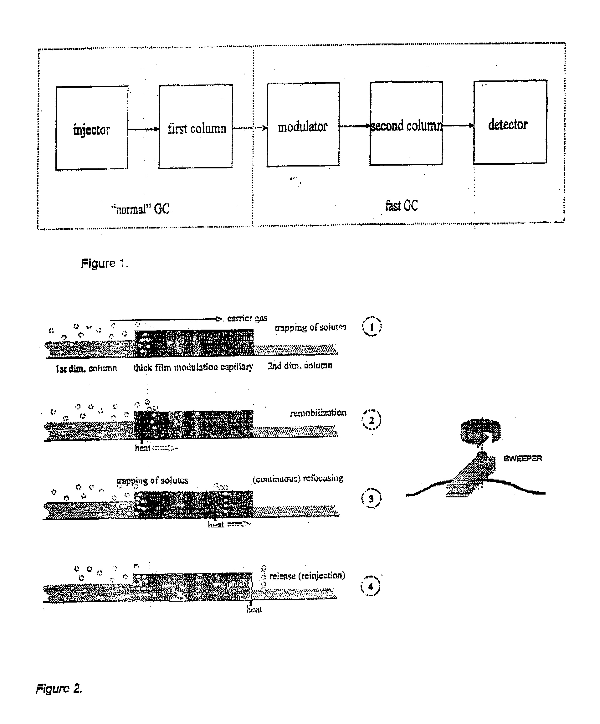
[0023] FIG. 1 is a scheme of the GCxGC system.

[0024] FIG. 2 is a scheme of the known heating modulation system (sweeper).

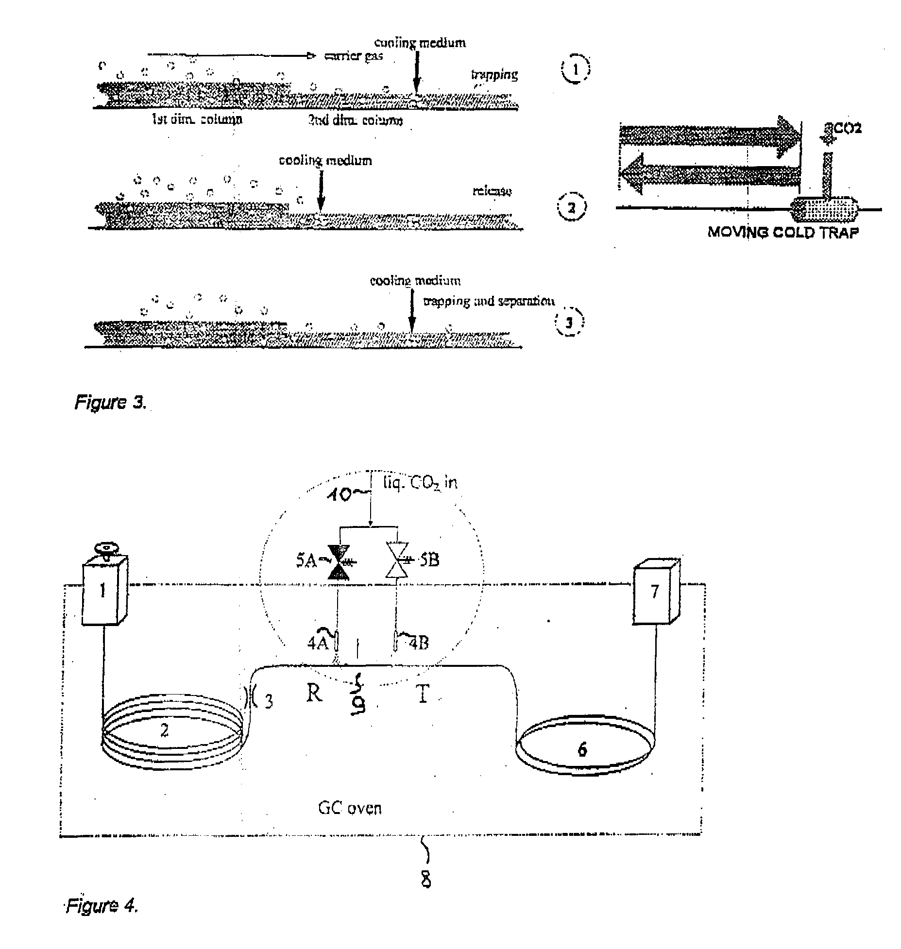
[0025] FIG. 3 is a scheme of the known cryogenic modulation system.

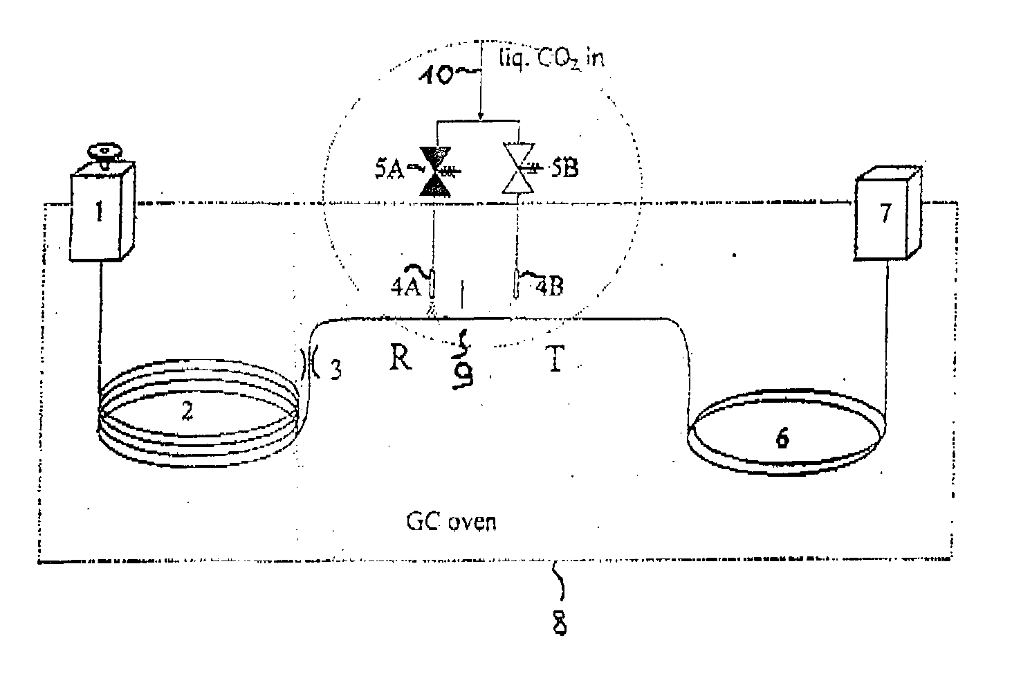
[0026] FIG. 4 is a scheme of a modulator according to the present invention.

[0027] FIG. 5 is a detail of the jet configuration of the modulator of FIG. 5.

[0028] FIG. 6 is a chromatogram obtained by means of a GCxGC separation of C.sub.8 through C.sub.18 with a modulator according to the present invention.

[0029] FIG. 7 is a chromatogram obtained by means of a GCxGC separation with a modulator according to the invention and showing the shape of the modulated n-C.sub.14 peaks.

[0030] FIG. 8 is a scheme of a modulator according to the present invent...


PUM

PropertyMeasurementUnit
timeaaaaaaaaaa
cycle timeaaaaaaaaaa
lengthaaaaaaaaaa

Abstract

This invention relates to a modulator for use in gas chromatographic analysis, adopted for alternatively trapping and releasing fractions of solutes in a length of a capillary column within a chromatographic oven, characterized in that it comprises at least one nozzle placed to spray at least one jet in at least one corresponding place along said capillary column length, said nozzle(s) being connected each to a source of liquid CO2 via a related valve, and means for alternatively opening said valve(s) for a predetermined time, to cause a jet of liquid CO2 to impinge for said predetermined time on said column place and to leave the oven atmosphere to heat said column place after said predetermined time. The modulator can be used in a conventional GC system or in a two dimensional GC system, for modulating the analytes fed to the second capillary column.

Description

[0001] This invention relates to a modulator for modulating sample fractions in a capillary column during a gas chromatographic analysis.[0002] The modulator according to the present invention can be designed for a traditional gas chromatographic apparatus in order to enhance the sensitivity by narrowing the peaks when placed directly in front of the detector or to focus the injected analytes when placed directly after the injector. However, it con also specially designed for comprehensive two dimensional gas chromatography.STATE OF THE ART[0003] The comprehensive two dimensional gas chromatography, also called comprehensive 2D GC, or GCXGC, is a gas chromatographic technique in which the sample is first separated on a conventional normal-bore high-resolution capillary GC column in the programmed temperature mode. All of the effluent of this first column is then focused in a large number of extremely narrow (<100 ms) and adjacent fractions at regular, short intervals and subseque...

Claims


Application Information

Patent Timeline
Patent Type & Authority Applications(United States)
IPC IPC(8): G01N30/02G01N30/12G01N30/54G01N30/30G01N30/46G01N30/60G01N30/62G01N30/86
CPCG01N30/463G01N30/465G01N2030/025Y10T436/204998G01N2030/3023G01N2030/623Y10T436/25875G01N2030/122
Inventor BEENS, JAN
Owner THERMO ELECTON
Why Eureka
Try Eureka