Interface device

a technology of interface device and interface, which is applied in the direction of data switching details, data switching networks, time-division multiplexing selection, etc., can solve the problems of limited number of devices that can successfully accommodate to only a low-speed interface, not a high-speed interface, and limited number of devices

Inactive Publication Date: 2003-06-12
FUJITSU LTD
View PDF4 Cites 31 Cited by
  • Summary
  • Abstract
  • Description
  • Claims
  • Application Information

AI Technical Summary

Problems solved by technology

That is, only a limited number of devices have supported an interface which accommodates a plurality of channels in a single physical interface by time division multiplexing.
In addition, such limited number of devices can successfully accommodate to only a low-speed interface, not a high-speed interface.
Therefore, it is difficult to construct a WAN, which can flexibly accommodate to the advanced service, such as LAN.
To integrate, in a single a single integrated circuit, the packet switch 120 and a circuit which has such a variety of rates and many channels and performs frame processing is difficult to be realized in view of a circuit scale, an I / O, and a power consumption, and cost of parts is increased.
In case of (1), the number of I / O's of the integrated circuits, a part mounting area, and power consumption increase.
In case of (2) and (3), the performance of the packet switch 120 and the time division multiplexing switch 300 is limited, which leads to a bottleneck and causes a suppression of a system performance.
In case of (4), as described above, a plurality of in-device interfaces are required, which causes complication of devices and an increase in menu of units constituting the device.

Method used


Image

  • Interface device
  • Interface device
  • Interface device

Examples


embodiment (

2)

Transmission of Unicast Packet and Multicast Packet

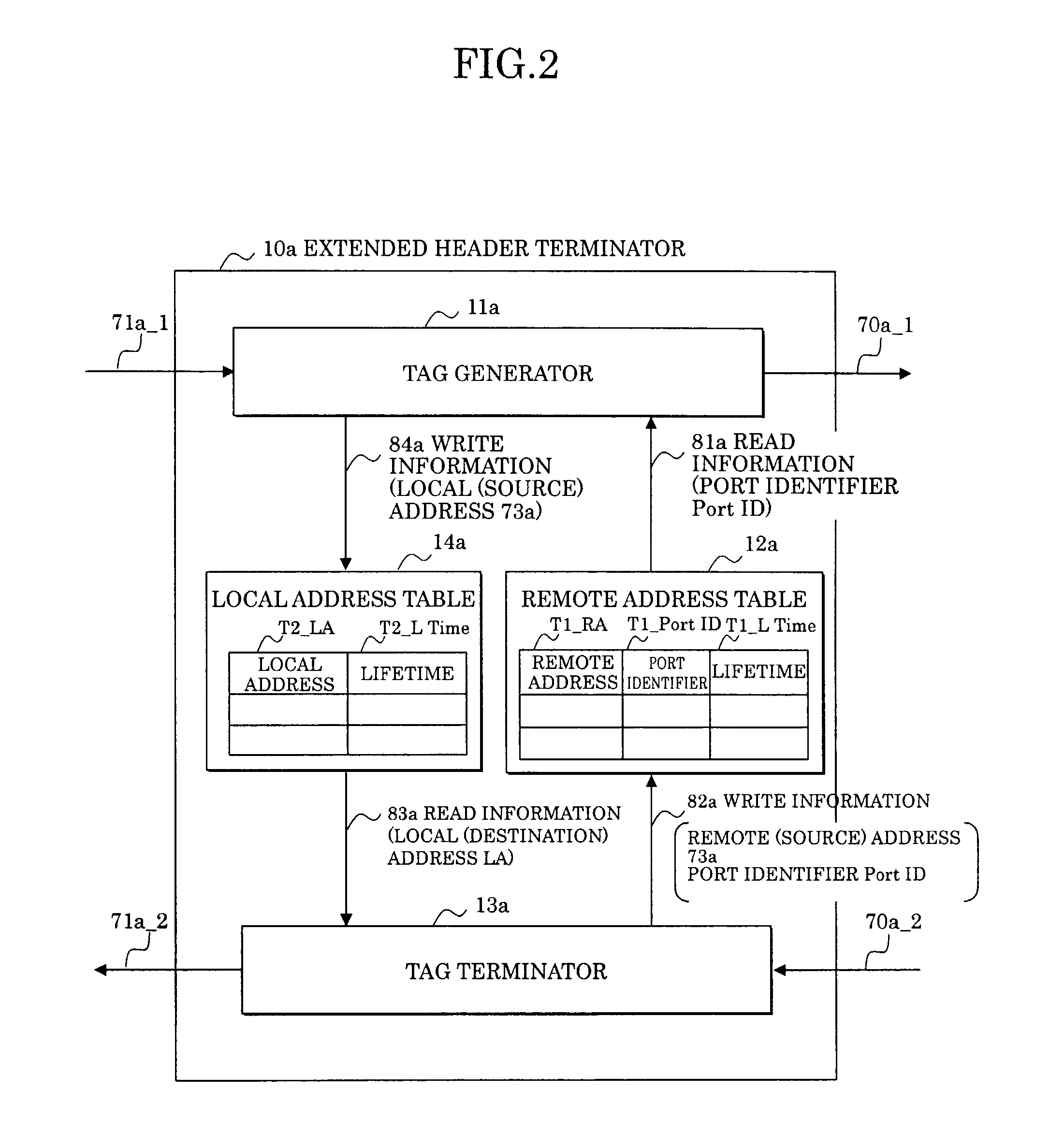
[0176] FIG. 8 shows an arrangement of an extended header terminator 10b in the embodiment (2) of the interface device 100 according to the present invention. This extended header terminator 10b is different from the extended header terminator 10a (see FIG. 2) of the embodiment (1) in that a group identifier field T1_GrpID for setting to the remote address table 12b a "group identifier GrpID" corresponding to the "remote address RA" is further provided.

[0177] An operation of a tag generator 11b is different from that of the tag generator 11a in the embodiment (1) (see FIG. 8) in that the "group identifier GrpID" corresponding to the destination address (remote address) of the packet 71b_1 is read from the remote address table 12b, and the "group identifier GrpID" is set in the group identifier field Tag_GrpID added to an in-device tag Tag_b.

[0178] In addition, an operation of a tag terminator 13b is different from that of the tag t...


PUM


Abstract

In an interface device connecting packet multiplexing networks and a time division multiplexing channel network having different multiplexing systems, and a network system, an address table associates a destination address with a broadcast identifier, a group identifier, and a port identifier uniquely indicative of a virtual concatenation channel for transmitting a packet to be stored, a tag generator of an extended header terminator, based on this address table, adds the broadcast identifier, the group identifier, and the port identifier to a received packet to be transmitted. A time division multiplexer of a frame processor having received this packet performs mapping on a virtual concatenation channel corresponding to the port identifier, and broadcasts or multicasts the packet according to the broadcast identifier and the group identifier.

Description

[0001] 1. Field of the Invention[0002] The present invention relates to an interface device, and in particular to an interface device which mutually connects packet multiplexing networks and a time division multiplexing channel network having different multiplexing systems, and a network system.[0003] A network system for long distance / high-speed transmission manages information by a time-division-multiplexed channel or path to be transmitted. For example, PDH (Plesiochronous Digital Hierarchy) and SHD (Synchronous Digital Hierarchy) respectively multiplex the information on a bit-by-bit or byte-by-byte basis to be transmitted.[0004] On the other hand, a transmission system for advanced service such as Quality of Service (QOS), broadcast, and multicast, and a network system of a user using a LAN (Local Area Network) multiplex the information on a packet basis (packet multiplexing) to be managed and transmitted.[0005] Recently, also in a WAN (Wide Area Network), needs for packet proc...

Claims


Application Information

Patent Timeline
Patent Type & Authority Applications(United States)
IPC IPC(8): H04J3/00H04J3/16H04L12/18H04L12/46H04L12/66H04Q11/04
CPCH04J3/1611H04L12/4604H04J2203/0094H04J2203/0082
Inventor YAMADA, SHIGEKI
Owner FUJITSU LTD
Why Eureka
Try Eureka