Rigid plate assembly with polishing pad and method of using

a technology of rigid plates and polishing pads, which is applied in the direction of flexible wheels, grinding machines, manufacturing tools, etc., can solve the problems of increasing the cost of the cmp process and the downtime of the cmp equipment, and the difficulty of a technician to replace the polishing pads

Inactive Publication Date: 2003-06-19
ORIOL
View PDF5 Cites 26 Cited by
  • Summary
  • Abstract
  • Description
  • Claims
  • Application Information

AI Technical Summary

Problems solved by technology

It is well-known that polishing pads tend to wear unevenly during polishing, causing surface irregularities to develop on the pad and on the work piece.
Since the rotatable platen is typically two to three feet in diameter, it is difficult for a technician to replace a polishing pad while the polishing pad and rotatable platen are within the processing chamber.
Although the previously described methods and apparatus for replacing a polishing pad are designed to facilitate replacing a polishing pad, they each require the introduction of a second device having multiple moving parts and / or introduces additional elements and features which may become worn and / or require maintenance.
The introduction of such a second apparatus or device in facilitating the replacement of a polishing pad significantly increases the cost of the CMP process as well as the downtime for the CMP equipment.
The introduction and installation of complex electromagnets embedded within the rotatable platen significantly increases the cost of the CMP equipment and may protrude from the top surface of the rotatable platen, thereby yielding an inconsistent surface for positioning a top plate member thereon.
Furthermore, the introduction of specialized bi-layer pads increases the cost of the CMP apparatus.

Method used


Image

  • Rigid plate assembly with polishing pad and method of using
  • Rigid plate assembly with polishing pad and method of using
  • Rigid plate assembly with polishing pad and method of using

Examples


Embodiment Construction

made in conjunction with the accompanying figures.

[0018] The principles of the present invention will hereinafter be described in conjunction with the appended figures, wherein like numerals denote like elements:

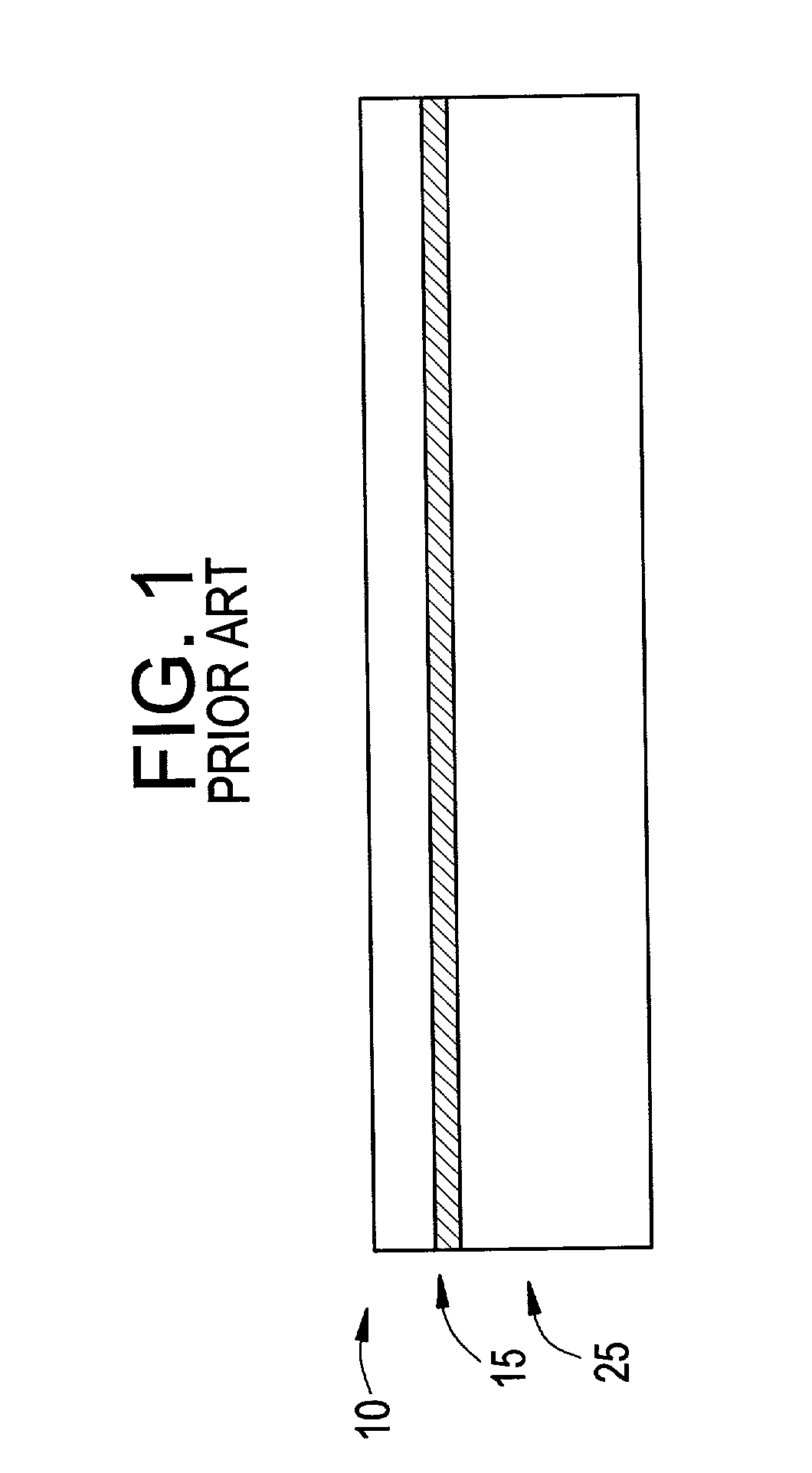
[0019] FIG. 1 is schematic view of a polishing pad currently known in the art;

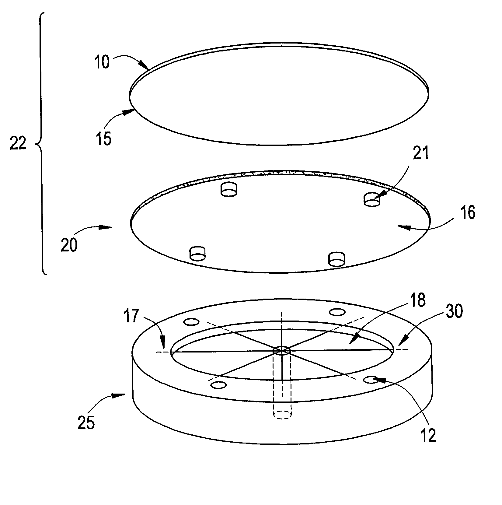
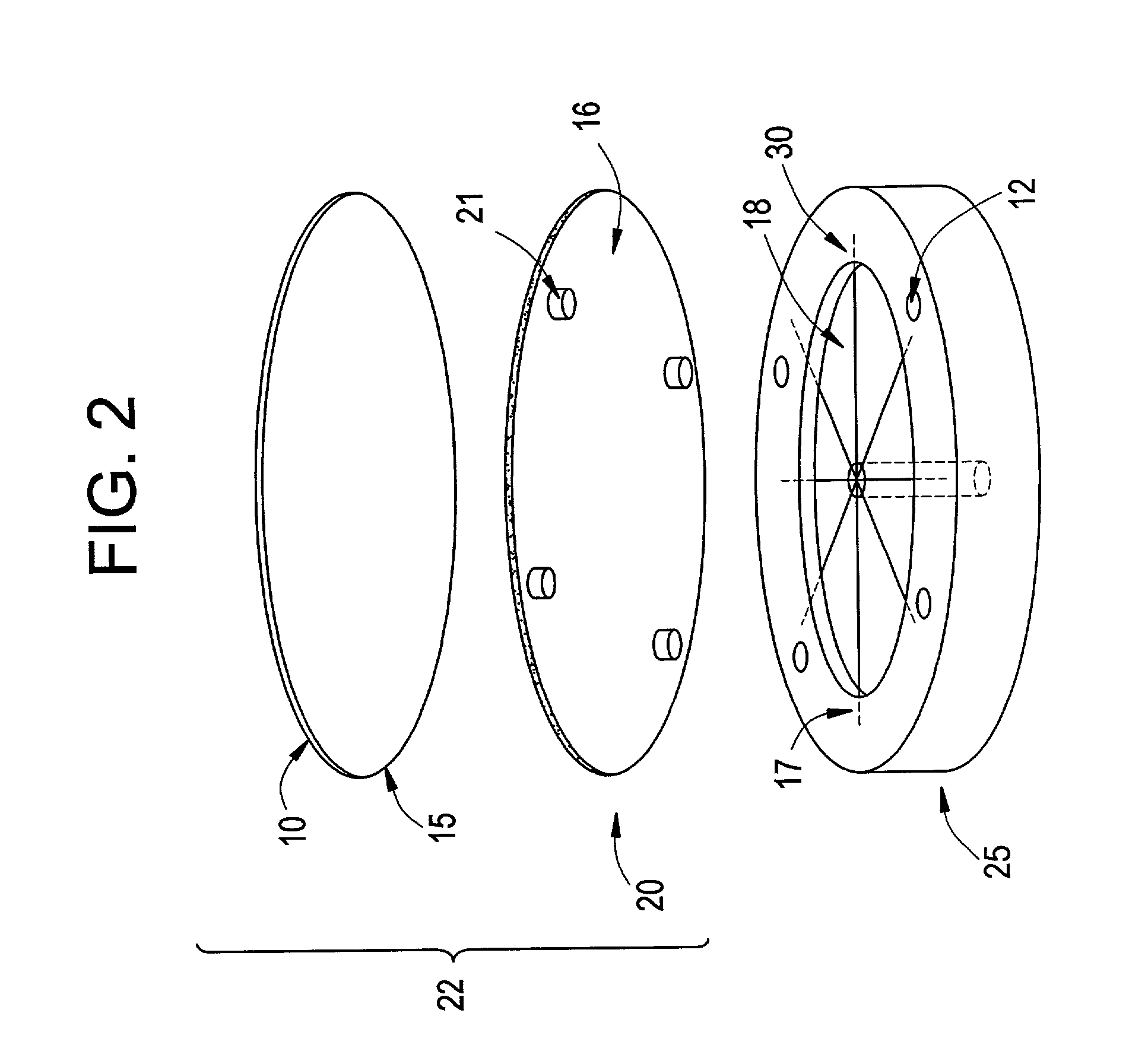
[0020] FIG. 2 is a three dimensional blow up view of a rigid plate assembly according to the principles of the present invention;

[0021] FIG. 3 is a schematic view of a rigid plate assembly according to the principles of the present invention;

[0022] FIG. 4 is a schematic view of the vacuum channel arranged within a rotatable platen according to the principles of the invention; and

[0023] FIG. 5 is a schematic view of the vacuum source according to the principles of the invention.

[0024] Referring now to FIGS. 2, 3, and 5, a CMP apparatus in accordance with the principles of the present invention includes a polishing pad (10) attached to a top surface of a rigid plate member (20) via adhesive material ...


PUM

PropertyMeasurementUnit
diameteraaaaaaaaaa
vacuumaaaaaaaaaa
vacuum forceaaaaaaaaaa

Abstract

An apparatus according to the principles of the present invention includes a rotatable platen, a rigid plate member with a top surface and a bottom surface, includes pin members coupled to the rigid plate member which can be inserted into guide openings positioned within the rotatable platen, and a vacuum channel formed within the platen that enables removable mounting the rigid plate member to a top surface of the rotatable platen. The vacuum channel includes a cavity in the top surface of the platen. The rigid plate member adhesively holds the polishing pad to form a rigid plate assembly. A vacuum source coupled to the vacuum channel can be activated to create a vacuum within the vacuum channel to attract the rigid plate member to the platen. The platen can then used to polish work pieces contacting the polishing pad on the top surface of the rigid plate member. PATENT

Description

[0001] 1. Field of the Invention[0002] The present invention generally relates to polishing and planarizing work pieces. More particularly, the present invention relates to a method and apparatus for implementing replacement of polishing pads used for polishing and planarizing work pieces.[0003] 2. Discussion of the Related Art[0004] Chemical mechanical polishing (CMP) is a well known planarizing method. CMP includes attaching one side of the wafer to be polished to a flat surface of a work piece carrier or chuck and pressing the other side of the work piece against a flat polishing pad. Polishing pads can be made of various materials which are commercially available. Typically, a polishing pad is made of blown polyurethane. The hardness and density of a polishing pad depends on the material that is to be polished. In CMP, a slurry containing a particulate abrasive such as cerium oxide, aluminum oxide, or fumed / precipitated silica is applied to a horizontal polishing pad during poli...

Claims


Application Information

Patent Timeline
Patent Type & Authority Applications(United States)
IPC IPC(8): B24B37/12B24D9/10B24D13/14
CPCB24D9/10B24B37/12
Inventor BERKSTRESSER, DAVIDJEONG, IN KWON
Owner ORIOL
Why Eureka
Try Eureka