Electroactive polymer actuator and diaphragm pump using the same

a technology of electroactive polymer actuators and diaphragm pumps, which is applied in the direction of positive displacement liquid engines, engine diaphragms, machines/engines, etc., can solve the problems of difficult control of the diaphragm deformation during the pumping operation, the deformation force of the diaphragm is relatively small, and the deformation speed of the diaphragm is relatively slow

Inactive Publication Date: 2003-06-26
MATSUSHITA ELECTRIC WORKS LTD
View PDF4 Cites 44 Cited by
  • Summary
  • Abstract
  • Description
  • Claims
  • Application Information

AI Technical Summary

Benefits of technology

[0019] A further concern of the present invention is to provide an electroactive polymer actuator characterized by a unique arrangement of laminates described below, which includes the capability of improving response speed and operation reliability of a device using electroactive effect. That is, this actuator comprises:
[0022] Another concern of the present invention is to provide an electroactive polymer actuator characterized by a spiral structure formed by winding an elongated laminate described below, which includes the capability of improving response speed and operation reliability of a device using electroactive effect. That is, this actuator comprises:

Problems solved by technology

However, in the case of using this laminate 10P as the diaphragm, it is difficult to control the deformation of the diaphragm during the pumping operation.
In addition, since the diaphragm is formed by the laminate 10P including the single thin-sheet member 12P of the electroactive polymer material, there are problems that a deformation force of the diaphragm is relatively small, and a deformation speed thereof is relatively slow.
Thus, it is said that these problems are causes of preventing the actual use of the devices such as the small-sized diaphragm pump using the electroactive effect.

Method used


Image

  • Electroactive polymer actuator and diaphragm pump using the same
  • Electroactive polymer actuator and diaphragm pump using the same
  • Electroactive polymer actuator and diaphragm pump using the same

Examples


first embodiment

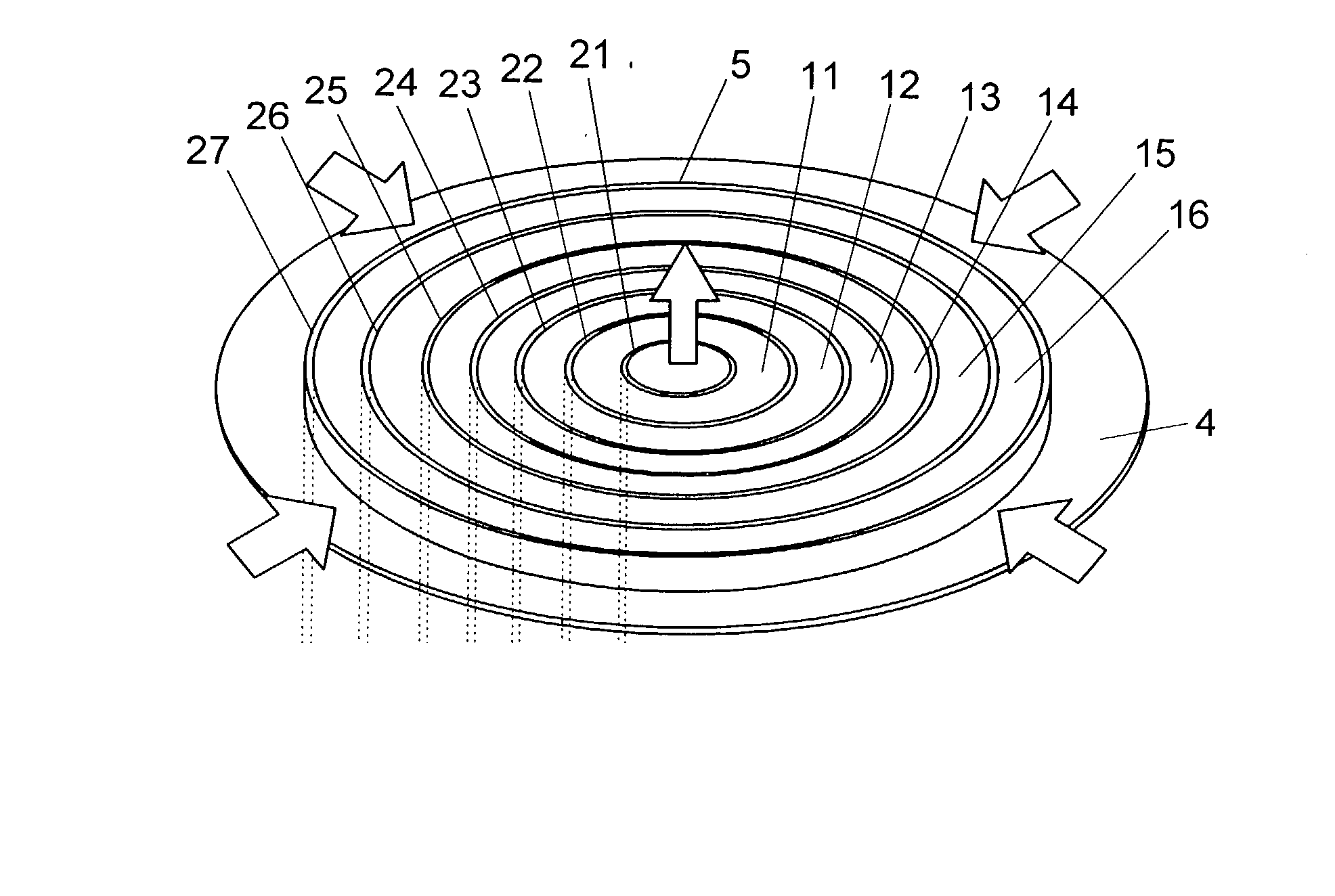
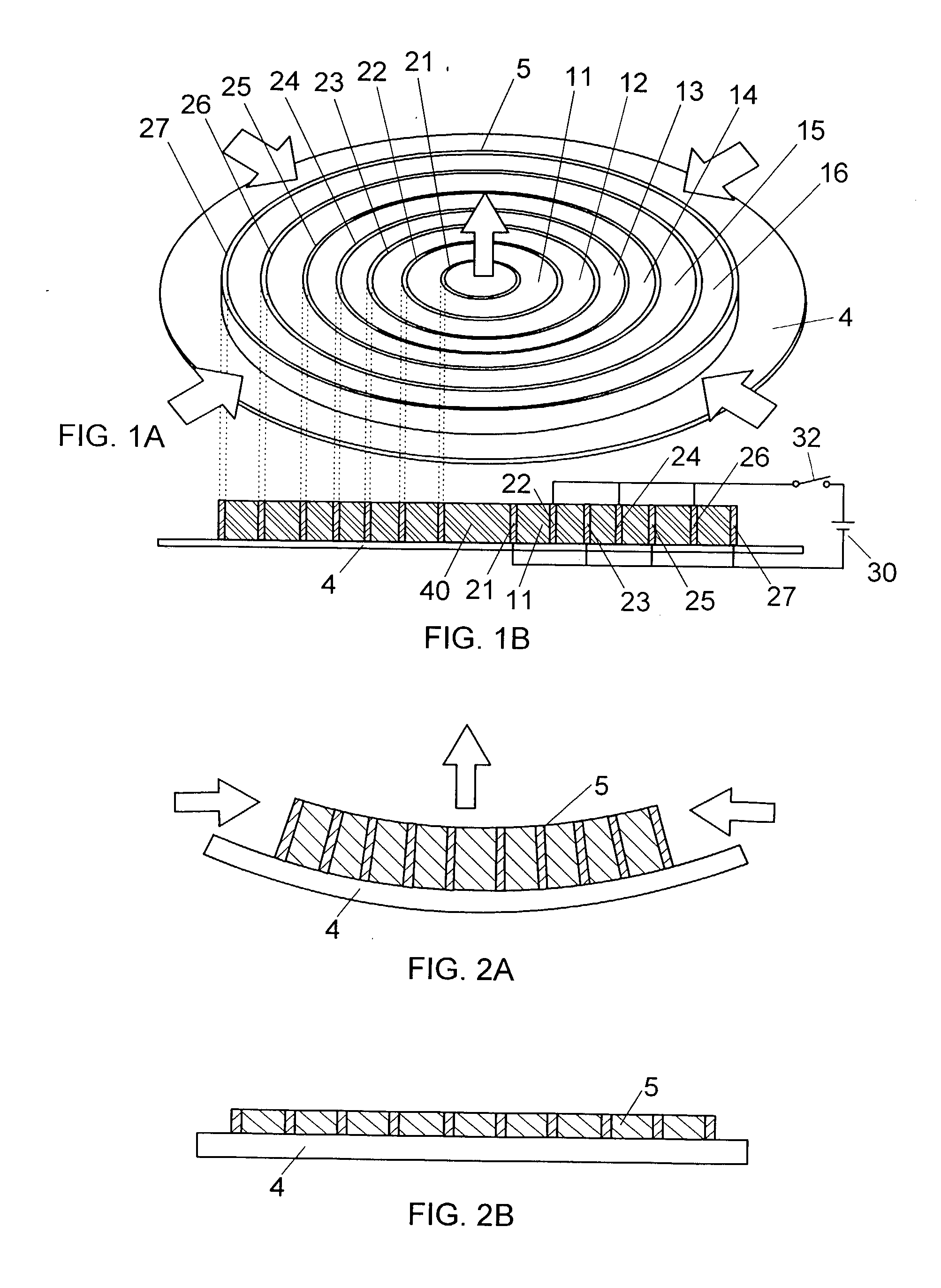
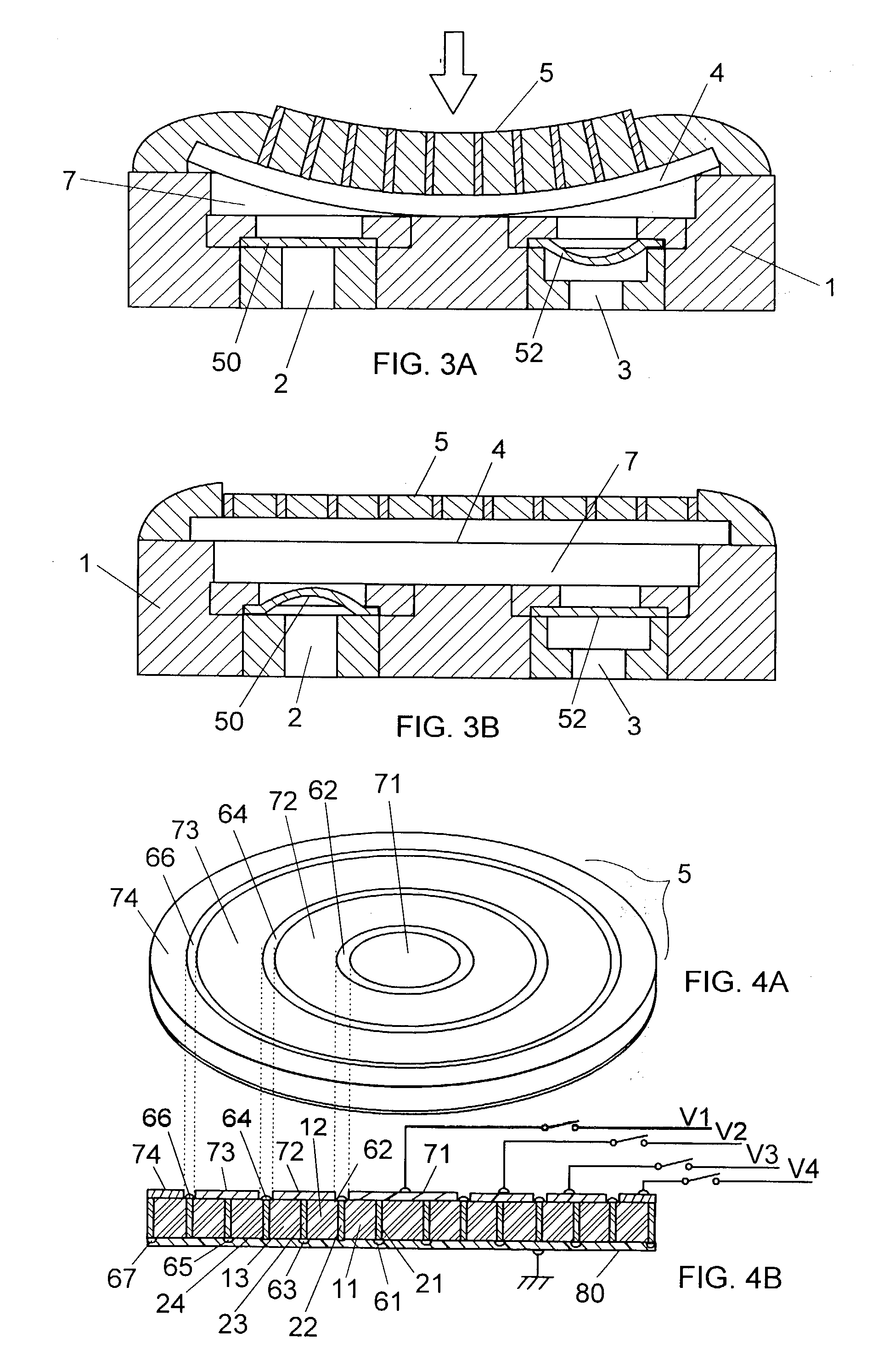
[0041] As shown in FIGS. 1A and 1B, an electroactive polymer actuator of the first embodiment has a disk-shaped laminate 5, which is formed by alternately placing first to sixth ring members 11 to 16 having different diameters of an electroactive polymer material such as silicon rubber and an acrylic material, and first to seventh ring electrodes 21 to 27 having different diameters in a concentric pattern such that each of the ring members is positioned between inner and outer peripheral surfaces of adjacent ring electrodes. In FIG. 1A, the numeral 4 designates a flexible thin sheet as a diaphragm, which is attached to a bottom surface of the laminate 5.

[0042] For example, the first ring electrode 21 can be obtained by forming a conductive layer on an inner peripheral surface of the first ring member 11, and the second ring electrode 22 can be obtained by forming a conductive layer on an outer peripheral surface of the first ring member 11. To form the conductive layer, for example,...

second embodiment

[0062] As shown in FIG. 9, an electroactive polymer actuator according to the present invention has an arrangement of a plurality of laminates 5A each having a triangular prism shape. Each of the laminates 5A includes a plurality electrodes 20A and electroactive polymer materials 10A, which are alternately placed in a direction of a vertical line extending from a vertex P of a triangle that is a general surface of the triangular prism to a base S of the triangle. In this embodiment, the number of the laminates is 8.

[0063] Those laminates 5A are arranged as a whole in an octagonal pattern such that the vertex P of the triangle is positioned in the vicinity of a center of the octagonal pattern, and each of the laminates 5A is spaced from an adjacent laminate by a required distance d. This actuator also has a voltage applying unit (not shown) for applying a voltage between the electrodes 20A of each of the laminates to cause a deformation in the laminate. By simultaneously applying the...

third embodiment

[0065] As shown in FIG. 10, an electroactive polymer actuator of the third embodiment has a spiral structure 5B formed by winding a laminate including an elongated sheet 10B of an electroactive polymer material such as silicon rubber and an acrylic material, a pair of electrode layers (21B, 22B) formed on both surfaces of the elongated sheet, and an insulation layer 60B formed on the electrode layer 22B. The insulation layer 60B prevents short circuit between the electrode layers (21B, 22B) in the spiral structure.

[0066] This actuator also has a voltage applying unit for applying a voltage between the electrode layers to cause a deformation in the spiral structure 5B. By applying the voltage between the electrode layers (21B, 22B) of the spiral structure 5B, a diaphragm 4B attached to the spiral structure 5B can be bent as in the case of the first embodiment, as shown by the arrows in FIG. 10.

[0067] In the above first to third embodiments, a unimorph type diaphragm drive unit, which...


PUM


Abstract

An electroactive polymer actuator, which has the capability of improving response speed and operation reliability of a device utilizing an electroactive effect, comprises a laminate formed by alternately placing a plurality of ring members of an electroactive polymer material having different diameters and a plurality of ring electrodes having different diameters such that each of the ring members is positioned between inner and outer peripheral surfaces of adjacent ring electrodes, and a voltage applying unit for applying a voltage(s) between odd-numbered ring electrodes and even-numbered ring electrodes in the case of counting the ring electrodes in order from an innermost ring electrode of the laminate, to thereby cause a deformation in the laminate. This actuator is preferably used as a diaphragm drive unit of a diaphragm pump.

Description

[0001] 1. Field of the Invention[0002] The present invention relates to an electroactive polymer actuator, which is preferably used for devices such as small-sized diaphragm pumps, and a diaphragm pump using the actuator.[0003] 2. Disclosure of the Prior Art[0004] In the past, for devices such as small-sized diaphragm pumps, it has been proposed to use a laminate composed of a sheet of an electroactive polymer material such as silicon rubber and an acrylic material, and a pair of electrode layers formed on both surfaces of the sheet. When a voltage is applied between the electrode layers, a deformation of the laminate happens such that a dimension in the thickness (vertical) direction of the laminate decreases, and the dimension in the horizontal direction of the laminate increases. This phenomenon is known as electroactive effect.[0005] For example, Japanese Patent Early Publication [kokai] No. 2001-263486 discloses a diaphragm pump using the electroactive effect. That is, as shown...

Claims


Application Information

Patent Timeline
Patent Type & Authority Applications(United States)
IPC IPC(8): F04B43/00H01L41/08F04B43/04H01L41/09H01L41/338H01L41/45H02N1/00H02N2/00
CPCF04B43/0054H01L41/0973H02N1/002F04B43/04H10N30/2047F16J3/02
Inventor URANO, YOUJIKITAHARA, HARUNORI
Owner MATSUSHITA ELECTRIC WORKS LTD
Why Eureka
Try Eureka