High loft low density nonwoven webs of crimped filaments and methods of making same

Inactive Publication Date: 2003-06-26
KIMBERLY-CLARK WORLDWIDE INC
View PDF22 Cites 63 Cited by
  • Summary
  • Abstract
  • Description
  • Claims
  • Application Information

AI Technical Summary

Problems solved by technology

However, in such constructions the fibers of the web still remain in the plan

Method used


Image

  • High loft low density nonwoven webs of crimped filaments and methods of making same
  • High loft low density nonwoven webs of crimped filaments and methods of making same
  • High loft low density nonwoven webs of crimped filaments and methods of making same

Examples


Embodiment Construction

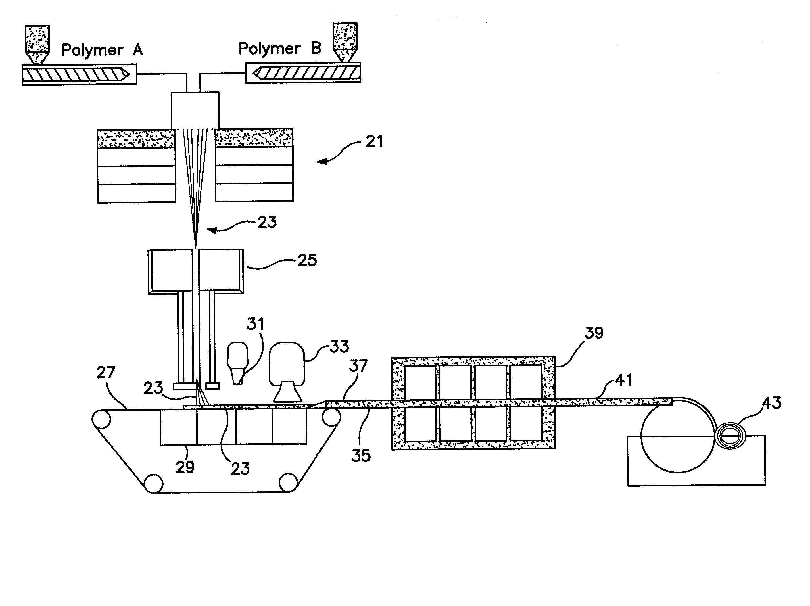
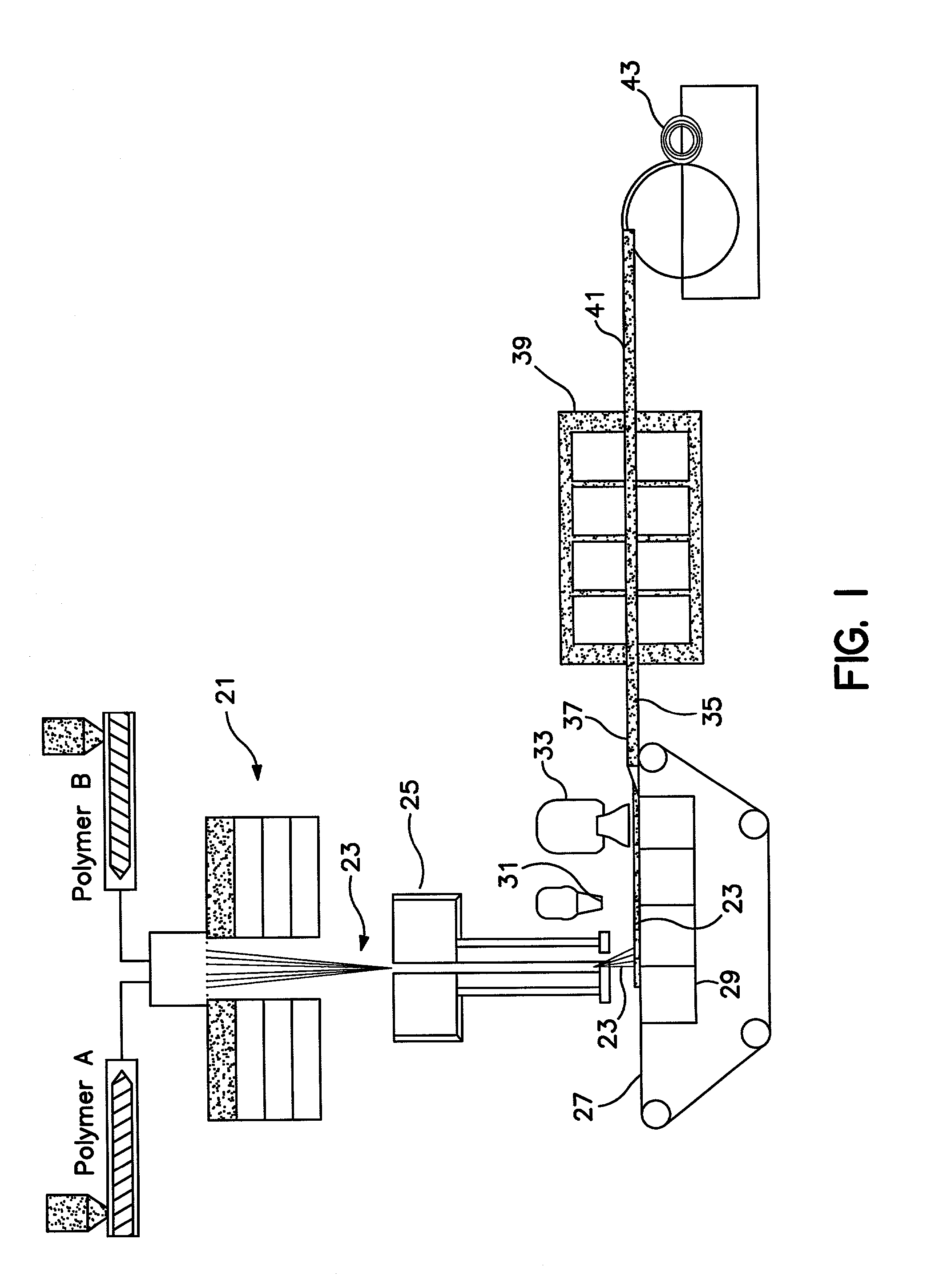
[0027] FIG. 1 is a schematic diagram illustrating methods and apparatus of this invention for producing high loft, low density materials by producing crimpable bicomponent side by side substantially continuous fibers and causing them to crimp in an unrestrained environment.

[0028] As shown in FIG. 1, two polymers A and B are spunbond with known thermoplastic fiber spinning apparatus 21 to form bicomponent side by side, or A / B, morphology fibers 23. The fibers 23 are then traversed through a fiber draw unit (FDU) 25. According to one embodiment of the present invention, unlike the standard practice in the art, the FDU is not heated, but is left at ambient temperature. The fibers 23 are left in a substantially continuous state and are deposited on a moving forming wire 27. Deposition of the fibers is aided by an under-wire vacuum supplied by a negative air pressure unit, or below wire exhaust, 29.

[0029] The fibers 23 are then heated by traversal under one of a hot air knife (HAK) 31 or...


PUM

PropertyMeasurementUnit
Lengthaaaaaaaaaa
Lengthaaaaaaaaaa
Lengthaaaaaaaaaa

Abstract

High loft, low density nonwoven webs are produced by forming substantially continuous, spunbond, crimped, bicomponent fibers of A/B side by side morphology in an unheated fiber draw unit. The fibers are then heated and cooled in the absence of impeding forces to achieve maximum crimp in the z-direction and produce a web of lofted material. The resultant material is particularly suitable for use as an insulator. Particulates may be added to the webs if desired.

Description

[0001] This invention relates to a high loft, low density nonwoven material produced from continuous fibers in which the lofty character of the nonwoven material is the result of the fibers comprising the web having a z-direction orientation, resulting from improved processing and the resultant crimping. These materials are particularly suitable for use in a broad range of applications including, without limitation, surge layers for personal care products, acoustic and thermal insulation, packing material, padding, absorbents, filtering, and cleaning materials.DISCUSSION OF THE RELATED ART[0002] In nonwoven webs, the fibers comprising the web are generally oriented in the x-y plane of the web and the resulting nonwoven web material is relatively thin, that is lacking in loft or significant thickness.[0003] Loft or thickness in a nonwoven web suitable for use in personal care absorbent articles promotes comfort (softness) to the user, surge management and fluid distribution to adjace...

Claims


Application Information

Patent Timeline
IPC IPC(8): D04H1/50D04H3/005D04H3/16D04H3/02
CPCD04H1/50Y10T428/2924Y10T428/2922D04H3/16Y10T442/681Y10T442/629Y10T442/632Y10T442/638D04H3/02D04H3/005
Inventor POLANCO, BRAULIO A.FENWICK, CHRISTOPHER DALECLARK, DARRYL FRANKLINHAYNES, BRYAN DAVIDBROWN, KURTIS LEEFREESE, CHAD MICHAEL
Owner KIMBERLY-CLARK WORLDWIDE INC
Why Eureka
Try Eureka