Liquid crystal display device, backlight used for same display device, method for driving same backlight and method for manufacturing same backlight

a technology of display device and liquid crystal, which is applied in static indicating devices, instruments, non-linear optics, etc., can solve the problems of unavoidable rise in fabrication costs, component count increase, and unsatisfactory performance of conventional lcds

Inactive Publication Date: 2003-07-03
GETNER FOUND L L C
View PDF8 Cites 89 Cited by
  • Summary
  • Abstract
  • Description
  • Claims
  • Application Information

AI Technical Summary

Benefits of technology

[0109] Also, a preferable mode is one wherein a partition wall is placed outside of a light emitting region for discharging in which scanning is initiated and invasion of light for discharging in a region in which discharging is kept continuously into a light emitting region for scanning is reduced.
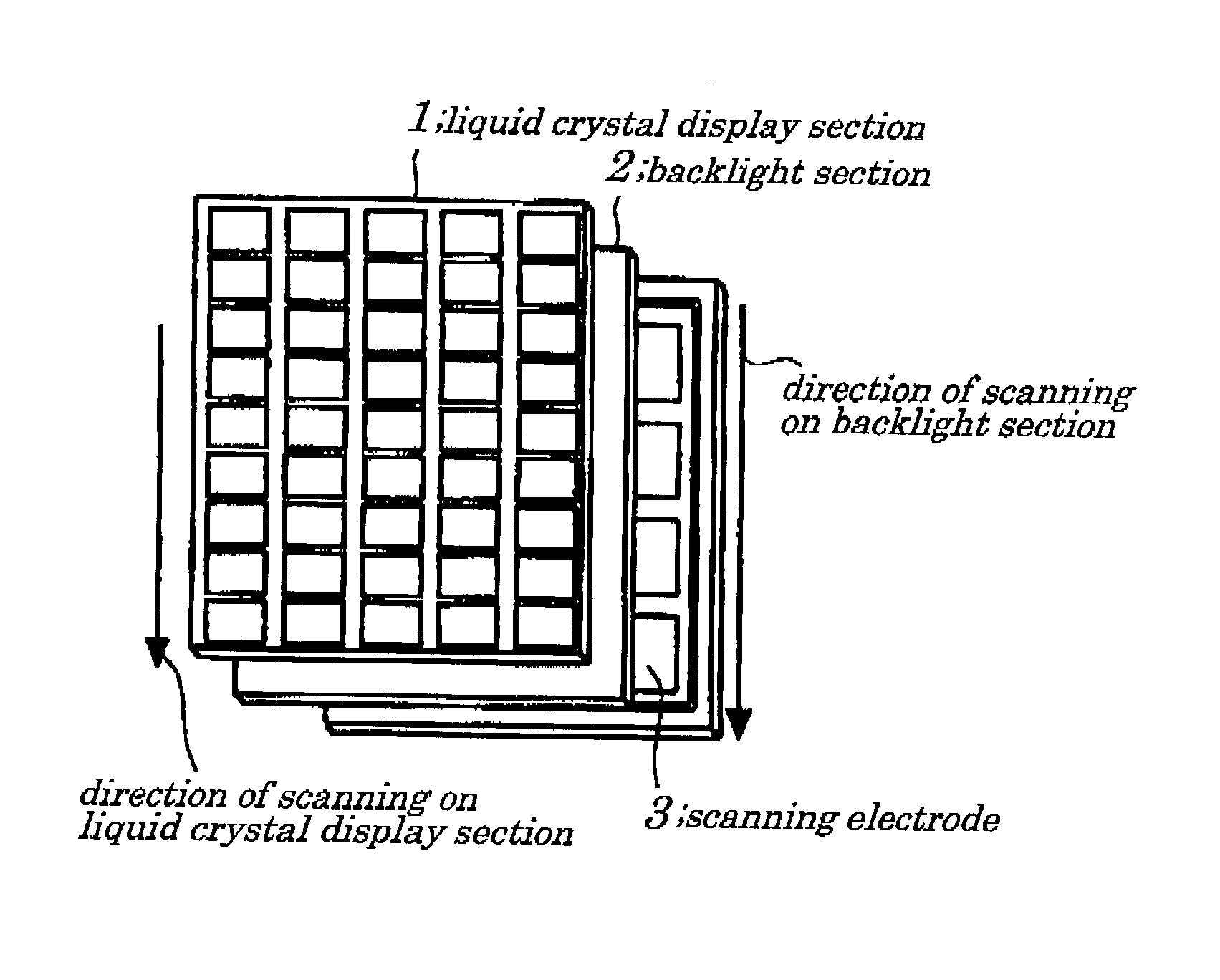
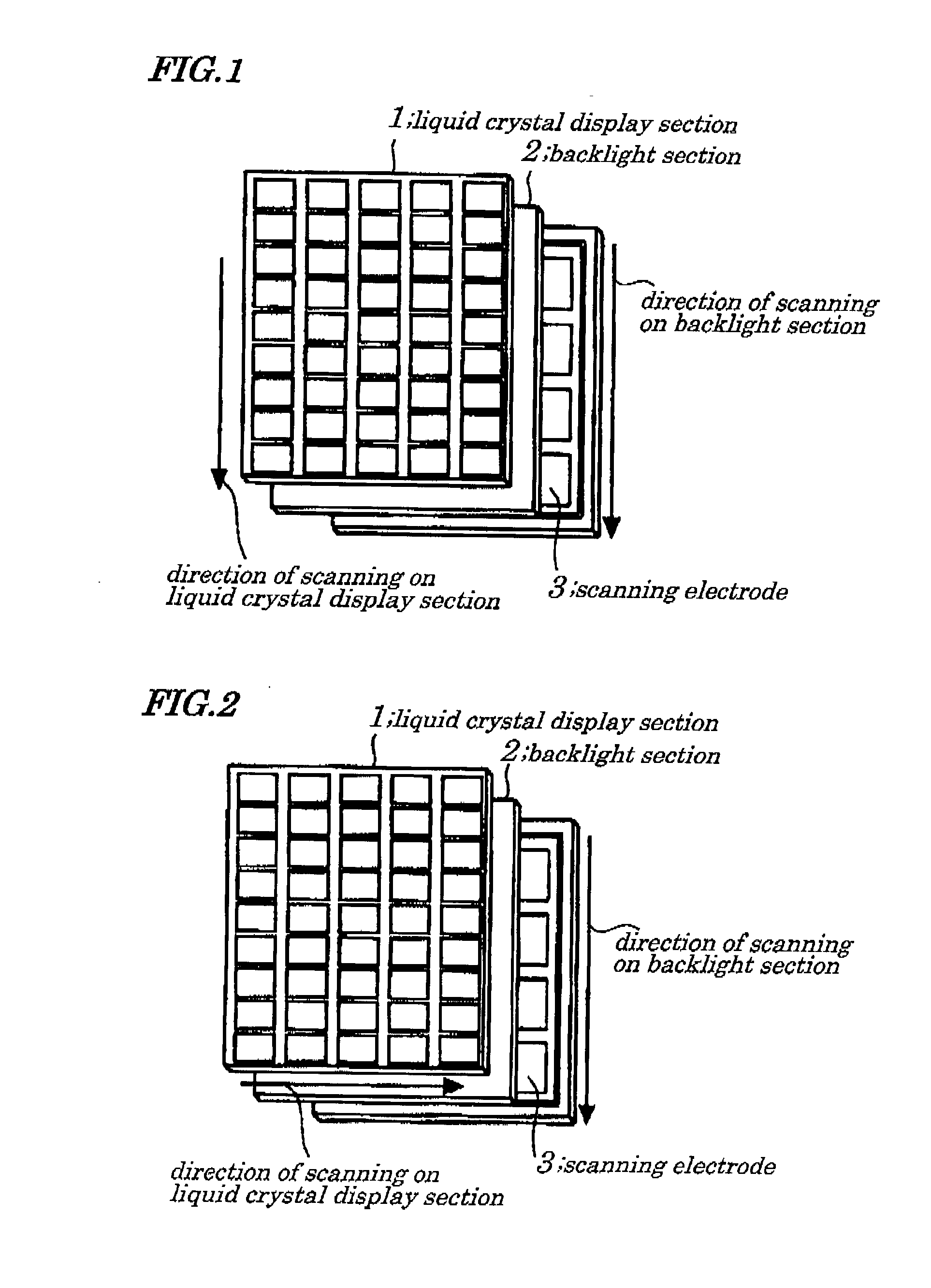
[0128] With the above configuration, a scanning electrode is formed internally in a backlight section and scanning is performed on a surface of the backlight section in a light emitting portion and, therefore, it is possible to reduce component counts, to simplify manufacturing processes, and to reduce costs. Also, since illuminating light emitted from the backlight is scanned and non-displaying period is provided, a performance of displaying moving pictures is improved.
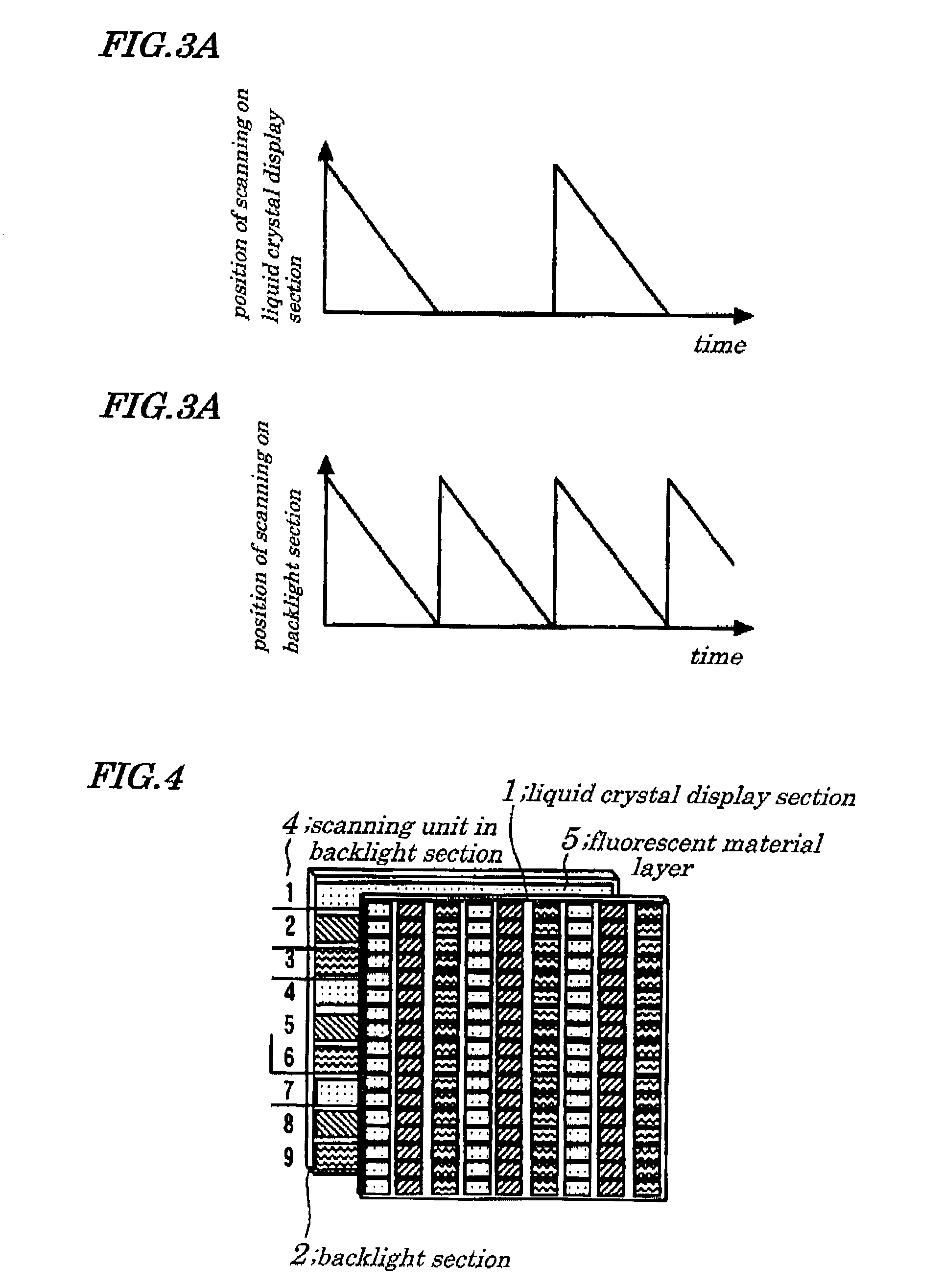
[0129] With another configuration, since one time scanning is performed on a screen in a liquid crystal display section within a predetermined period and two or more times scanning are performed on a screen in a backlight, occurrence of a flicker can be prevented.
[0130] With still another configuration, since a protrusion is formed on a side of discharging space existing between electrodes facing each other in a backlight, control can be exerted in a place in which discharge as seeds occurs and in a place in which strong discharging occurs, thus enabling uniform and stable discharging to be achieved.
[0131] With still another configuration, since an auxiliary discharging area is formed in a place being adjacent to a region being scanned in a backlight and, in this auxiliary discharging area, discharging occurs immediately before occurrence of discharging in a head portion of the region being scanned, or discharging is maintained all the time and, since excited atoms and molecules, electrons, or ions serving as seeds of discharge are fed, it is possible to have discharging that rises in a stable and speedy manner occur, as in the case of other region being scanned.
[0132] With still another configuration, since redundancy is provided to a scanning light emission region in a backlight, high reliability is given to a displaying characteristic of a liquid crystal display panel which performs driving for scanning by using the backlight.

Problems solved by technology

There are two main reasons for dissatisfactory performance of a conventional LCD.
These conventional backlight units adapted to apply light fed from the backlight in synchronization with timing of scanning on the LCD present problems in that component counts increase and a rise in costs for fabrication are unavoidable.
That is, when the LED is used, since many LEDs have to be arranged on a surface of the backlight, the increase in component counts and in assembling processes are unavoidable.
This presents a serious problem in the case of a large-screen-type LCD in particular.
Therefore, a price of the backlight rises in the case of the large-screen-type LCD.
Thus, in the conventional scanning-type backlight, though performance of displaying a moving picture is improved, costs for fabricating the backlight are high and therefore it is impossible to make low a price of the LCD device.
In the case of the simple matrix form, application of an excessive voltage to a pixel on a non-selected scanning line at a time of scanning on a screen causes low contrast.
If a scanning electrode is mounted at a back of the backlight section 2, emitting of light in a region between the scanning electrodes is made difficult.
As a result, uniform illuminating light on an entire screen is made impossible.
As a result, noise or a like are produced in the liquid crystal display device which causes a display failure.
In the LCD of the above embodiments, since a scanning electrode is placed for scanning, such the display failure presents a serious problem.
When the anti-EMI filter layer is mounted outside of the liquid crystal display section 1, a problem of a moire stripe caused by pitch drifts arises.
As a result, when compared with a conventional liquid crystal display device, more complicated taking-out of wires is required.

Method used


Image

  • Liquid crystal display device, backlight used for same display device, method for driving same backlight and method for manufacturing same backlight
  • Liquid crystal display device, backlight used for same display device, method for driving same backlight and method for manufacturing same backlight
  • Liquid crystal display device, backlight used for same display device, method for driving same backlight and method for manufacturing same backlight

Examples


Embodiment Construction

[0284] An example of the present invention will be described below. FIG. 35 is a cross-sectional view schematically illustrating basic configurations of a gas discharging-type backlight used in the present invention. In FIG. 35, in the backlight of the example of the present invention, a common electrode 102 made up of a transparent conductive film made by using an indium oxide or tin oxide as a main ingredient is formed on an entire surface of a displaying region of a first glass substrate 101. The first glass substrate 101 and the common electrode 102 make up a front glass substrate 100.

[0285] On a second glass substrate 201 is formed, in order to control a region of emitted light, short-book shaped scanning electrodes 202 fabricated by using a metal thin film or metal particles as a main ingredient which are arranged in parallel in a direction traveling straight to a scanning direction or a metal fine particle, on which a white dielectric layer 203 is formed and finally a fluores...


PUM

PropertyMeasurementUnit
wavelengthaaaaaaaaaa
frequencyaaaaaaaaaa
frequencyaaaaaaaaaa

Abstract

A Liquid Crystal Display (LCD), a backlight used for the LCD and a method for producing the LCD and the backlight are provided which are capable of inhibiting an increase in component counts and in assembling processes and of reducing them, thereby achieving low costs. A display image is obtained by arranging a backlight section being able to perform scanning as a single unit in a manner that it positionally matches a liquid crystal displaying section. The backlight section is provided with a plurality of scanning electrodes and light emitting layers each providing a different luminescent color, and being spatially separated from each other on a principal face of the backlight and scanning is performed on a plurality of light emitting layers providing a different luminescent color.

Description

[0001] 1. Field of the Invention[0002] The present invention relates to a liquid crystal display device, a backlight used for a same display device, a method for driving a same backlight and a method for manufacturing a same backlight.[0003] The present application claims priorities of Japanese Patent Application No. 2001-324873 filed on Oct. 23, 2001, which are hereby incorporated by reference.[0004] 2. Description of the Related Art[0005] In recent years, a remarkable improvement in performance of a liquid crystal display device (hereinafter being referred to an "LCD") is yielded and also a remarkable progress in making its screen larger is made. The LCD having a large screen is used as a monitor for a personal computer or a like. Development work of a liquid crystal television by expanding technology of the LCD with a large screen is actively proceeding.[0006] In such an application to the television, an improvement in performance of displaying a moving picture in an LCD is stron...

Claims


Application Information

Patent Timeline
Patent Type & Authority Applications(United States)
IPC IPC(8): G02F1/133G02F1/13357G09G3/34G09G3/36
CPCG02F1/133621G02F2001/133622G09G3/342G09G3/3611G09G3/3406G09G2310/0235G09G2310/024G09G2310/08G09G2320/0261G09G2300/02G02F1/133622
Inventor SUMIYOSHI, KENYOSHIOKA, TOSHIHIROHAYAMA, HIROSHIMATSUSHIMA, JIN
Owner GETNER FOUND L L C
Why Eureka
Try Eureka