Liquid crystal display device, substrate assembly for liquid crystal display device, and electronic apparatus

Inactive Publication Date: 2003-07-03
138 EAST LCD ADVANCEMENTS LTD
View PDF7 Cites 47 Cited by
  • Summary
  • Abstract
  • Description
  • Claims
  • Application Information

AI Technical Summary

Problems solved by technology

However, in reflective liquid crystal display devices, since display is performed using outside light such as natural light or illumination light, there has been a problem in that it has been difficult to view the display in a dark place.
Accordingly, for example, in the case in which the color filter having pale tints is used so as to preferentially display colors in a reflective display mode in which light passes twice through the color filter, it is difficult to obtain fine color display in a transmissive display mode in which incident light passes through the color filter only once.
However, in order to solve the

Method used


Image

  • Liquid crystal display device, substrate assembly for liquid crystal display device, and electronic apparatus
  • Liquid crystal display device, substrate assembly for liquid crystal display device, and electronic apparatus
  • Liquid crystal display device, substrate assembly for liquid crystal display device, and electronic apparatus

Examples


first embodiment

[0058] First Embodiment

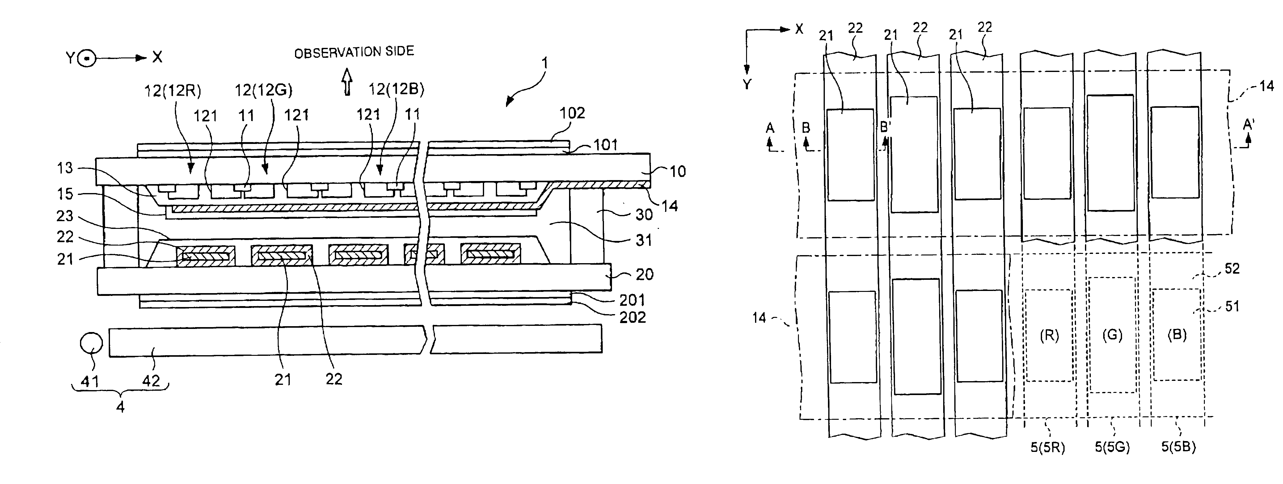
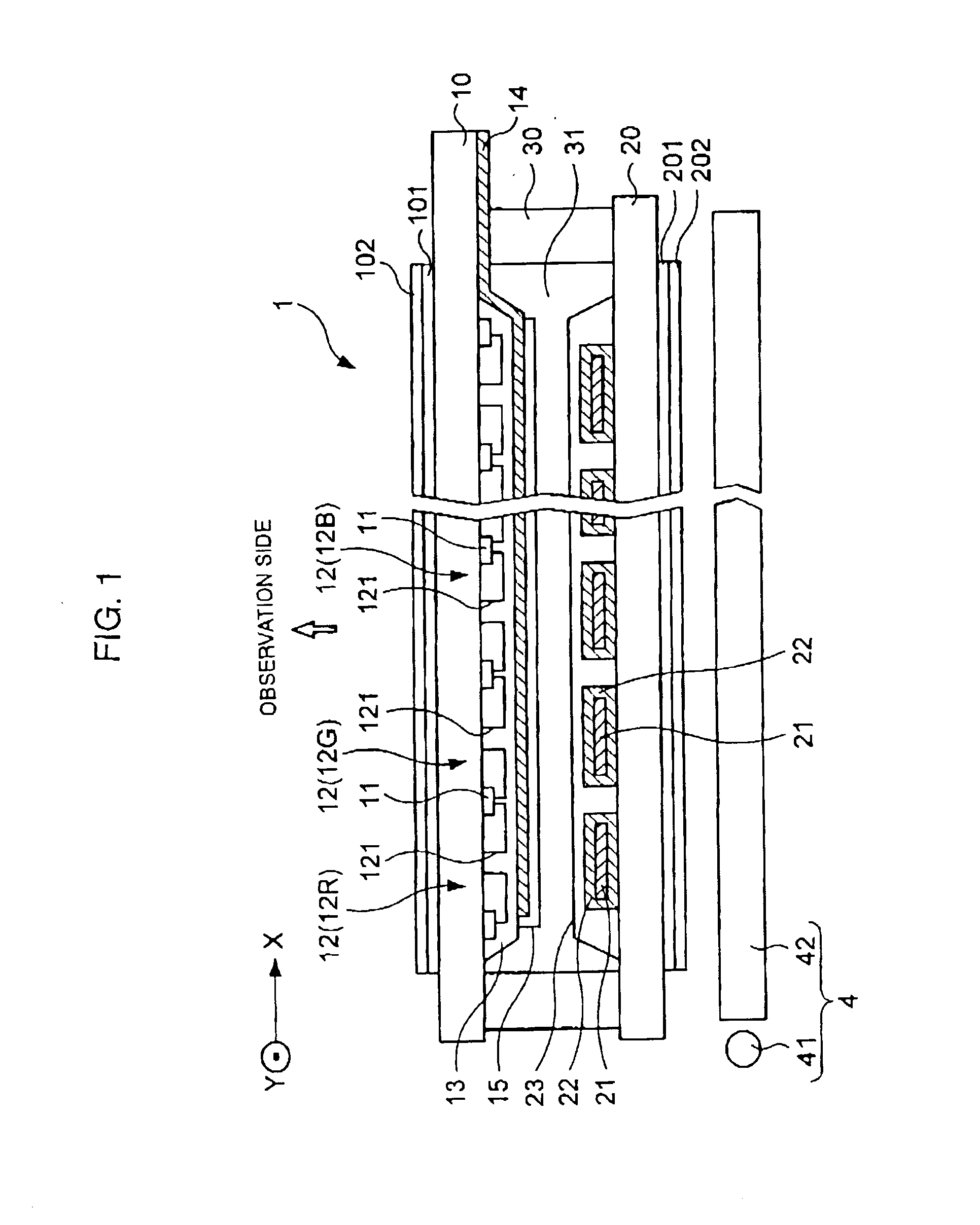
[0059] First, referring to FIG. 1, an embodiment in which the present invention is applied to a passive matrix type transflective liquid crystal panel will be described. As shown in the figure, a liquid crystal display device comprises a liquid crystal panel 1 and a backlight unit 4. The liquid crystal panel 1 has the structure in which a first substrate (upper substrate) 10 and a second substrate (lower substrate) 20 opposing thereto are bonded to each other with a sealing material 30 provided therebetween, and liquid crystal 31 such as a TN (twisted nematic) or a STN (super twisted nematic) type is enclosed in a region surrounded by the two substrates described above and the sealing material 30. The backlight unit 4 is disposed at the second substrate 20 side of the liquid crystal panel 1. Hereinafter, as shown in FIG. 1, a side opposite to the backlight unit 4 with respect to the liquid crystal panel 4 is called "observation side". That is, the "observation...

second embodiment

[0087] Second Embodiment

[0088] Next, a liquid crystal panel according to a second embodiment of the present invention will be described.

[0089] In the first embodiment, the structure in which the shading layer 11, the color filters 12, and the overcoat layer 13 are provided on the first substrate 10 located at the observation side is described by way of example. In this embodiment, the structure in which the elements described above are provided on the second substrate 20 is formed.

[0090] FIG. 8 is a cross-sectional view showing the structure of the liquid crystal panel of this embodiment, and FIG. 9 includes a plan view and a cross-sectional view showing the positional relationship between dots, color filters and reflective layers in the liquid crystal panel. The same reference numerals of the constituent elements of the liquid crystal panel 1 according to the first embodiment designate the equivalent constituent elements shown in FIGS. 8 and 9.

[0091] As shown in FIGS. 8 and 9, on t...

first modified embodiment

[0098] First Modified Embodiment

[0099] In the first and the second embodiments described above, in order to compensate for the difference in transmittance properties among the color filters 12 corresponding to different colors, the areas of the reflective layer 21 and the opening portion 121 of the color filter 12G corresponding to the green dot 5G are made different from those corresponding to the red dot 5R and blue dot 5B, and, in addition, the areas of those described above corresponding to the red dot, green dot, and blue dot may be made different from each other. In addition, in the embodiments described above, the areas of the reflective layers 21 and the areas of the opening portions 121 of the color filters 12 corresponding to the individual color dots are made different from each other in accordance with the transmittance properties of the color filters 12, and in addition, the areas described above corresponding to the individual color dots may be made different from each...


PUM


Abstract

A transflective color liquid crystal display device in which fine colors can be displayed in both a reflective display mode and a transmissive display mode. The transflective liquid crystal display device comprises a pair of substrates; a liquid crystal layer between the pair of substrates; reflective films are provided on an internal surface of a lower substrate which reflects light incident from an upper substrate; color filters provided above the reflective films, each containing a plurality of color layers which have different colors and are disposed to correspond to dots forming a display region; and lighting means provided at the outer surface side of the lower substrate. The dots have a reflective region in which the reflective film is present and a transmissive region in which the reflective film is not present. In addition, the color filters have opening portions in regions that overlap the reflective film in each dot.

Description

[0001] The present invention relates to liquid crystal display devices, substrate assemblies used for liquid crystal display devices, and electronic apparatuses, and more particularly, relates to a transflective liquid crystal display device having superior visibility, in which sufficiently bright display can be performed not only in a transmissive display mode but also in a reflective display mode.[0002] Since electrical power consumption has been small since light sources such as a backlight are not provided, reflective liquid crystal display devices have been widely used for various portable electronic apparatuses. However, in reflective liquid crystal display devices, since display is performed using outside light such as natural light or illumination light, there has been a problem in that it has been difficult to view the display in a dark place. Accordingly, a liquid crystal display device has been proposed in which display can be viewed in a bright place by using outside lig...

Claims


Application Information

Patent Timeline
IPC IPC(8): G02F1/1335
CPCG02F1/133514G02F2203/09G02F1/133555G02F1/1335
Inventor IIJIMA, CHIYOAKIHAGIWARA, TAKESHI
Owner 138 EAST LCD ADVANCEMENTS LTD
Why Eureka
Try Eureka