Apparatus and method for processing image signal and imaging equipment

a technology of image signal and apparatus, applied in the direction of color television details, television system details, television systems, etc., can solve the problems of deterioration of s/n ratio, camera cannot correctly follow the shooting object, noiseless clear image cannot be obtained in this way,

Inactive Publication Date: 2003-07-10
SONY CORP
View PDF4 Cites 13 Cited by
  • Summary
  • Abstract
  • Description
  • Claims
  • Application Information

AI Technical Summary

Problems solved by technology

Thus, the camera cannot correctly follow the shooting object.
If, in an attempt to increase the margin of the dynamic range, illumination is dimmed or an amount of light entering the solid-state image pickup device is reduced by decreasing the aperture of the object lens, a level of the dark current will not vary but only the intensity of the image signal decreases, thereby resulting in deterioration of the S/N ratio.
Hence, a noiseless clear image

Method used


Image

  • Apparatus and method for processing image signal and imaging equipment
  • Apparatus and method for processing image signal and imaging equipment
  • Apparatus and method for processing image signal and imaging equipment

Examples


Embodiment Construction

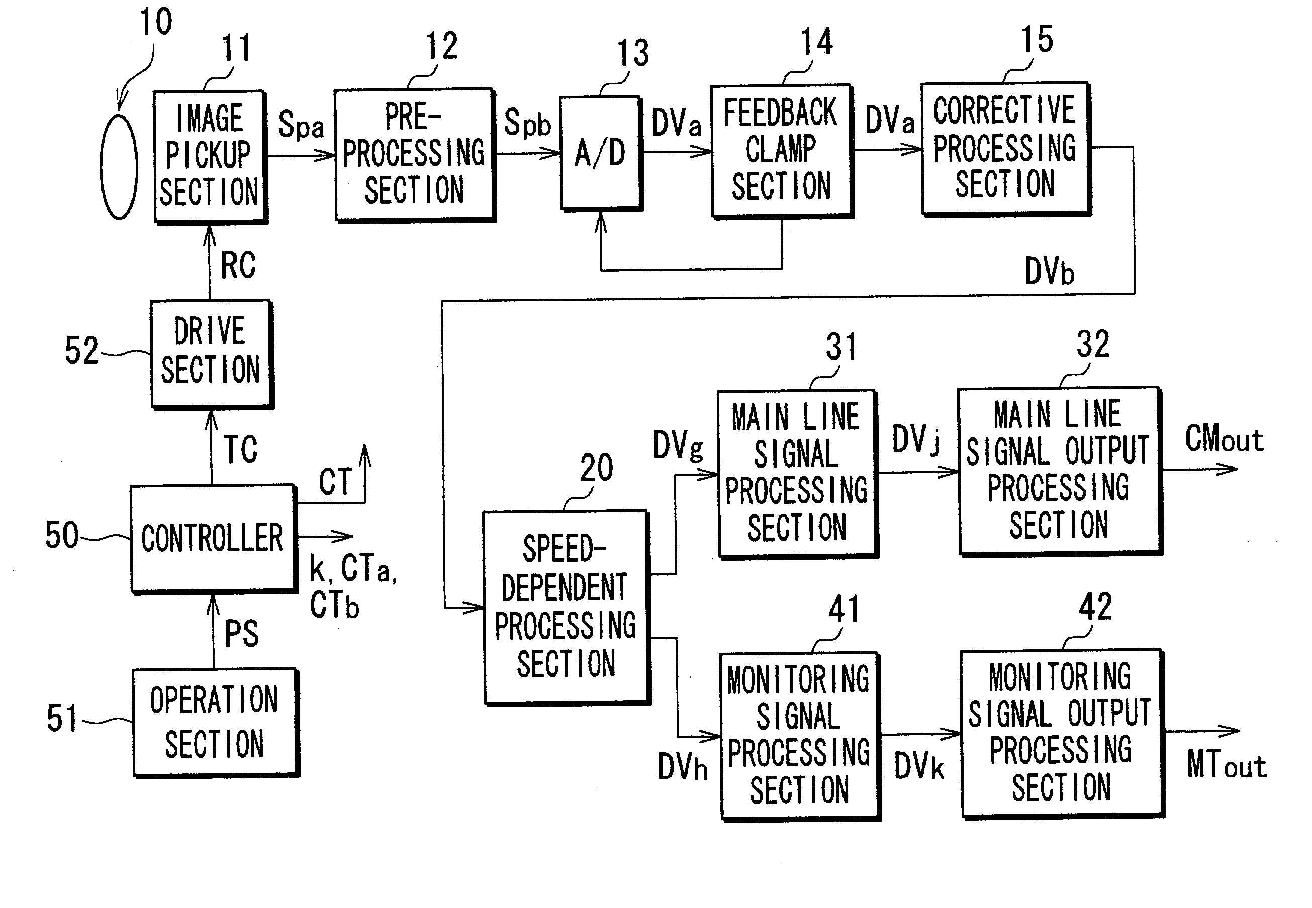
[0028] The invention will now be described in detail by way of example with reference to the accompanying drawings. FIG. 4 shows an arrangement of a video camera. Incident beam of light enters through an imaging lens 10 into an imaging pickup section 11 and then an image of an object is formed on the imaging surface of the imaging pickup section 11. The image pickup section 11 is formed of a solid-state image pickup device, e.g. CCD. The image pickup section 11 retrieves, based on a drive signal RC received from a drive section 52 as described later, a signal associated with a picture of the object obtained through photoelectric conversion of the image of the object. The section 11 generates RGB signals Spa, for example, on the imaged picture, and supplies the resultant RGB signals to a pre-processing section 12.

[0029] The pre-processing section 12 executes noise-component-removing processing (e.g. correlated double sampling) on the image signal Spa to remove therefrom noise compone...


PUM


Abstract

An image pickup device picks up an image. An image signal in association with the image is filtered in a time axis direction using a digital low-pass filter to generate an image signal having a reduced dynamic resolution power, which is equivalent to an image signal that would be obtained at a longer exposure time. The filtered signal is then subjected to frame skipping processing to generate an output image signal having a preferred frame period. The resultant signal is equivalent to one obtained by a slow shooting.

Description

[0001] 1. Field of the Invention[0002] This invention relates to an apparatus and a method for processing an image signal, and imaging equipment.[0003] 2. Description of Related Art[0004] In the field of conventional movie production, film cameras have been used. This type of film camera has a mirror 81 mounted on a rotary disk shutter 80 off the open area of the shutter, and an imaging lens 70 and a ground glass 82 of an optical viewfinder aligned on the optical axis of the mirror 81 as shown in FIG. 1. When the rotary disk shutter 80 is positioned in the open area, photographed object images are formed on a film 83, exposing the film 83. Then this stops displaying the photographed object images on the optical viewfinder. When the rotary disk shutter 80 is positioned in the non-open area, frame stepping is carried out for the film 83, with the photographed object images reflected by the mirror 81 and displayed on the ground glass 82 of the optical viewfinder.[0005] Regulation of th...

Claims


Application Information

Patent Timeline
IPC IPC(8): H04N5/225H04N5/232H04N5/14H04N5/262H04N5/335H04N5/345H04N5/353H04N5/361H04N5/363H04N5/367H04N5/378H04N5/765
CPCH04N5/217H04N5/2625H04N5/23293H04N23/81H04N23/65
Inventor SUDO, FUMIHIKO
Owner SONY CORP
Why Eureka
Try Eureka