Collecting apparatus of floating dusts in atmosphere and method for measuring floating dusts

a technology of atmospheric collecting apparatus and floating dust, which is applied in the field of collecting, can solve the problems of difficult to extract floating dust individually, high toxicity, and difficult to do analyses

Inactive Publication Date: 2003-07-24
SHIMADZU CORP
View PDF10 Cites 55 Cited by
  • Summary
  • Abstract
  • Description
  • Claims
  • Application Information

AI Technical Summary

Problems solved by technology

Although these floating dusts contain sands, they are mainly composed of black smokes, unburned materials, sulfur compounds and the like (35% of these is generated from diesel engine cars in the Kanto District, Japan), and it is said that they are highly toxic.
In the collecting method using the filter to analyze SPM and PM2.5 with the microscope or various chemical analyzing instruments, it is very difficult to extract the floating dusts individually.
Also, in the case of conducting various chemical analyses, since the floating dusts are difficult to remove from the filter, it is difficult to do the analyses.
For example, in the case of a fluorescent X-ray analyzer, it is difficult to irradiate the X-ray only on the particles.
Further, it is difficult to conduct the spectrum analysis, since the floating dusts are not separated each other on the filter and electromagnetic wave is difficult to focus on a single particle.
Also, the gas chromatograph mass spectrometer or the like is difficult to apply as the floating dusts are hardly separated from the filter.
In the conventional method for measuring the concentration of the floating dusts, the filter is easy to absorb water, thereby causing an error in measuring the floating dusts due to the absorbed water.
Therefore, it is difficult to measure a real time change in the concentration, and the work is also troublesome.
However, the concentration of the floating dusts in the atmosphere is not constant and varies even during the collecting operation.
Thus, at the time point when the collecting is completed, the quantity of the floating dusts is totally different from an expected value, and it is difficult to obtain a sample at a desired concentration.
Also, it takes long time to collect the pollens on the surface of the slide glass, for example, 24 hours, in the conventional method for collecting the pollens floating in the atmosphere.
However, the information does not represent the whole pollens floating in the atmosphere since the collected pollens are influenced by wind and the like.
Further, it is necessary to measure the respective diameters of the pollens to obtain a particle size distribution of the pollens, resulting in a complicated work.
Therefore, even though it is desired that the particle size distribution be measured at a high resolution, there is a limitation.
In the conventional electrostatic-type particle collector as described above, it takes long time to manufacture the discharge electrode since a large number of metal wires need to be bundled together.
In addition, it is necessary to have a step of making one end thereof in a brush shape, resulting in a high cost.
Further, in addition to the cost, it is difficult to make the shape and structure of the discharge electrode uniform, resulting in a large variation in efficiency of generating the ions and collecting the particles in the particle collector.
However, when the laser beam is irradiated directly to the yellow sand particles in the atmosphere to measure the diffracted / scattered light, it is impossible to obtain the sufficient diffracted / scattered light for obtaining the particle size distribution due to a low concentration of the yellow sand particles in the atmosphere.
However, when the laser beam is directly irradiated to the pollens naturally floating in the atmosphere, it is impossible to obtain the sufficient diffracted / scattered light for obtaining the particle size distribution due to a very low concentration.

Method used


Image

  • Collecting apparatus of floating dusts in atmosphere and method for measuring floating dusts
  • Collecting apparatus of floating dusts in atmosphere and method for measuring floating dusts
  • Collecting apparatus of floating dusts in atmosphere and method for measuring floating dusts

Examples


Embodiment Construction

[0093] Hereunder, embodiments according to the present invention will be explained with reference to the accompanying drawings.

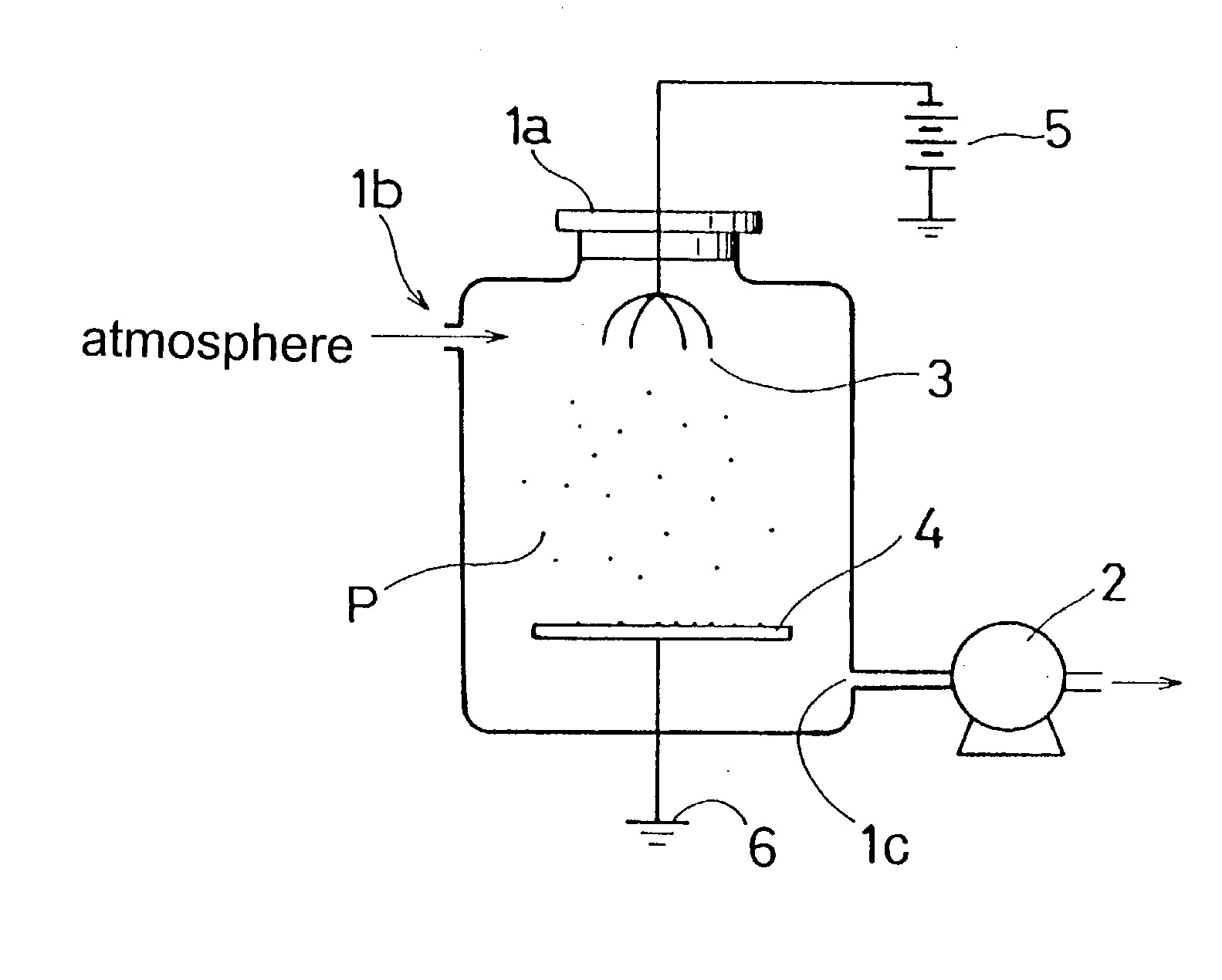
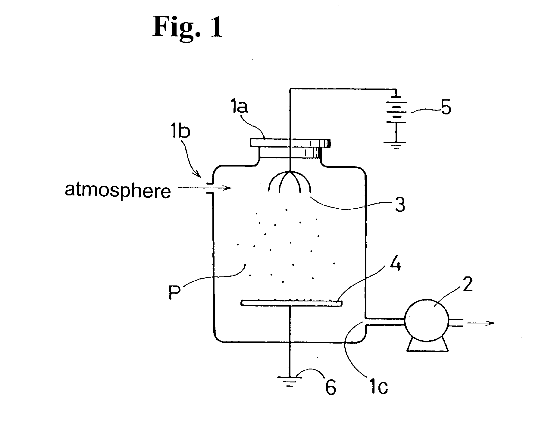
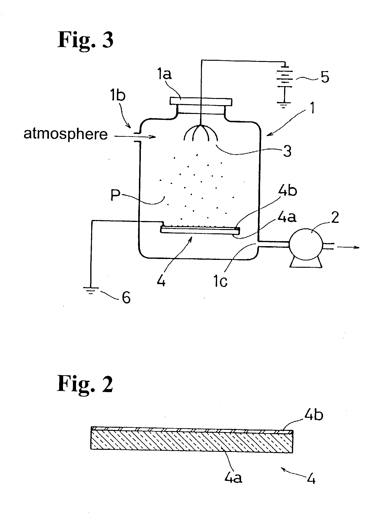
[0094] FIG. 1 is a schematic view for showing a structure of an embodiment of a collect device according to the present invention. A collecting container 1 has a lid 1a that opens and closes a top of the container. The collecting container also includes an inlet port 1b and a communicating port 1c. The communication port is connected to an inlet of a pump (compressor) 2, so that the pump 2 sucks the atmosphere into the collecting container 1 through the inlet port 1b in a state where the lid 1a is closed.

[0095] In the collecting container 1, a discharge electrode 3 is disposed at an upper portion thereof and a dust-collecting electrode 4 facing the discharge electrode 3 is positioned at a lower portion thereof. A high voltage is applied to the discharge electrode 3 from a high voltage source 5, so that the air near the discharge electrode 3 is ionized to pro...


PUM

PropertyMeasurementUnit
diameteraaaaaaaaaa
diametersaaaaaaaaaa
particle diametersaaaaaaaaaa

Abstract

A collecting device for collecting particles floating in the atmosphere includes a collecting container; a pump for sucking the atmosphere into the collecting container; a discharge electrode disposed in the collecting container for generating single polarity ions to charge the particles in the collecting container; and a dust-collecting electrode for collecting the charged particles in the collecting container through a potential difference between the discharge electrode and the dust-collecting electrode. The dust on the dust-collecting electrode is measured and analyzed.

Description

BACKGROUND OF THE INVENTION AND RELATED ART STATEMENT[0001] The invention relates to a collecting device for collecting floating dusts in the atmosphere; a method for measuring a particle size distribution of the floating dusts collected by the collecting device; and a method for measuring a quantity, shape and component of the floating dusts in the atmosphere.[0002] Among the fine particles floating in the atmosphere, those particles having a diameter less than 10 .mu.m are called suspended particle matter (SPM). Although these floating dusts contain sands, they are mainly composed of black smokes, unburned materials, sulfur compounds and the like (35% of these is generated from diesel engine cars in the Kanto District, Japan), and it is said that they are highly toxic. The dusts from the exhaust gas from the diesel engine car are specially called diesel exhaust particles (DEP). Also, the particles floating in the atmosphere having a particle smaller than 2.5 .mu.m are called micro...

Claims


Application Information

Patent Timeline
Patent Type & Authority Applications(United States)
IPC IPC(8): B01D49/00G01N1/22G01N1/24G01N1/28G01N15/02G01N15/06
CPCB01D49/00G01N1/2202G01N1/24G01N15/0211G01N15/0266G01N2001/2223B03C2201/24G01N2015/0693B03C3/368B03C3/41B03C3/47B03C2201/04B03C2201/10G01N2001/2833B03C3/53
Inventor TOTOKI, SHINICHIRO
Owner SHIMADZU CORP
Why Eureka
Try Eureka