Satellite broadcasting system

a satellite broadcasting and satellite technology, applied in the field of satellite broadcasting systems, can solve the problems of low degree of channel multiplex per frequency, inability to meet the requirement for more channels, and difficulty in solving multiplex schemas

Inactive Publication Date: 2003-07-24
SUENAGA MASASHI +4
View PDF0 Cites 60 Cited by
  • Summary
  • Abstract
  • Description
  • Claims
  • Application Information

AI Technical Summary

Benefits of technology

0060] According to still another aspect of the present invention, there is provided a satellite broadcasting receiver for receiving digital broadcasting using a geostationary satellite placed in a geostationary orbit above the equator, comprising timepiece means for counting time, view data detection means for detecting a channel received by the satellite broadcasting receiver and a reception time, an interface connectable to a recording medium on / from which data can be written / read, and view data recording control means for recording, on the recording medium connected to the interface, the reception channel and time detected by the view data detection means in correspondence with each other.

Problems solved by technology

In a system of this type, however, the degree of channel multiplex per frequency is low, so this system cannot meet a requirement for more channels, which has arisen along with recent advances in multimedia technologies.
However, these multiplex schema have various problems to be solved before they are applied to the satellite broadcasting system.
In some cases, important information may be lost during the channel switching period, and a measure is necessary.
In addition, unless the antenna is precisely directed to the satellite, no sufficient gain is obtained, and reception is disabled.
These systems assume indoor reception / viewing, so it is hard to provide a satellite broadcasting receiver using a simple antenna system meeting requirements for use on a mobile or use as a portable device.
Generally, when the reception terminal is moving, small obstacles frequently enter between the broadcasting satellite and the reception terminal.
A direct wave from the satellite cannot be received in an area behind buildings.
However, such a public reception system requires large-scale construction and enormous cost because cables must be laid to all users.
However, mobile stations behind the buildings cannot receive information from the satellite because no coaxial cables or optical cables can be laid to the mobile stations.
In satellite broadcasting systems of any types, when the number of broadcasting channels is increased, the output requirement for a repeater-side power amplifier on the satellite becomes high accordingly, so it is difficult to require an increase in number of broadcasting channels.
In addition, unless the antenna is precisely directed to the satellite, no sufficient gain is obtained, and reception is disabled.
These systems assume indoor reception / viewing, so it is hard to provide a satellite broadcasting receiver using a simple antenna system meeting requirements for use on a mobile or use as a portable device.
Since this channel selection operation is cumbersome and distracts the driver from driving, a traffic accident may be caused.
However, depending on the degree of fatigue of the driver, monotonous music may make the driver sleep, resulting in an adverse effect.

Method used


Image

  • Satellite broadcasting system
  • Satellite broadcasting system
  • Satellite broadcasting system

Examples


first embodiment

[0115] (First Embodiment)

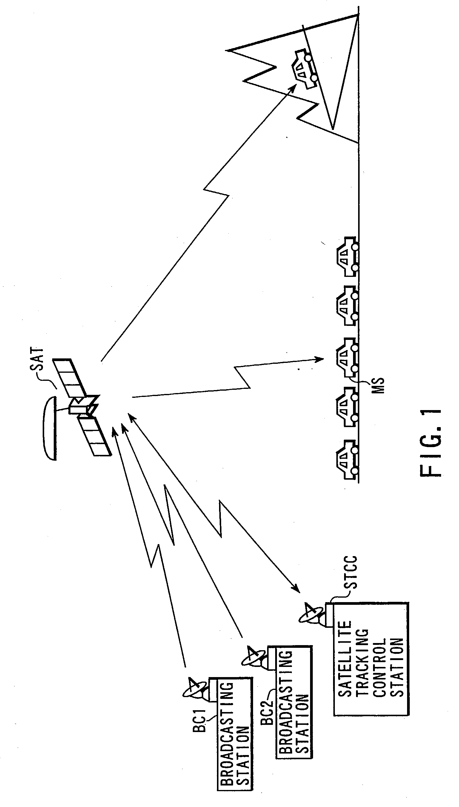
[0116] FIG. 1 is a schematic view showing a satellite broadcasting system according to the first embodiment of the present invention.

[0117] This satellite broadcasting system includes a plurality of ground broadcasting stations (VSAT) BC1 and BC2 or feeder link stations, a geostationary satellite SAT, and a satellite tracking control station STCC.

[0118] Each of the ground broadcasting stations (VSAT) BC1 and BC2 or the feeder link stations transmits program information prepared and edited by a broadcaster to the geostationary satellite SAT through an uplink transmission channel in the Ka band (26.5 to 40 GHz) or the Ku band (12.5 to 18 GHz).

[0119] The geostationary satellite SAT has a Ka-band or Ku-band antenna having a diameter of 2.5-m class and an S-band (e.g., 2.6 GHz) antenna having a diameter of 15-m class. A broadcasting signal multiplexed and transmitted from one of the broadcasting stations (VSAT) BC1 and BC2 or the feeder link stations is received ...

second embodiment

[0127] (Second Embodiment)

[0128] In the second embodiment of the present invention, a geostationary satellite SAT detects the spreading code phase difference between the channels of a CDM broadcasting signal arriving from each of a ground broadcasting station BC1 or BC2, matches the spreading code phases between the channels on the basis of the detection result, and then transmits a signal to a broadcasting receiver MS.

[0129] FIG. 3 is a block diagram showing the arrangement of the geostationary satellite SAT according to the second embodiment. Referring to FIG. 3 a CDM broadcasting signal transmitted from the ground broadcasting station BC1 or BC2 is received by a Ku-band reception antenna 151 and input to a reception circuit 152. The CDM broadcasting signal is low-noise-amplified, down-converted into an IF signal, and distributed to k correlators 161 to 16k. The number of correlators 161 to 16k is set in correspondence with a total number k of channels to be multiplexed / transmitte...

third embodiment

[0135] (Third Embodiment)

[0136] In the third embodiment of the present invention, a ground broadcasting station BC1 or BC2 detects the spreading code phase difference between channels in generating a CDM broadcasting signal and transmitting the CDM broadcasting signal, and the phase difference information is multiplexed to the CDM broadcasting signal and transmitted. In selectively receiving one of the channels of the CDM broadcasting signal arriving through a geostationary satellite SAT, a broadcasting receiver MS initializes the chip phase of the spreading code on the basis of the phase difference information received together with the CDM broadcasting signal, and selectively despreads the spectrum of the broadcasting signal of each channel using the spreading code to reconstruct the broadcasting signal.

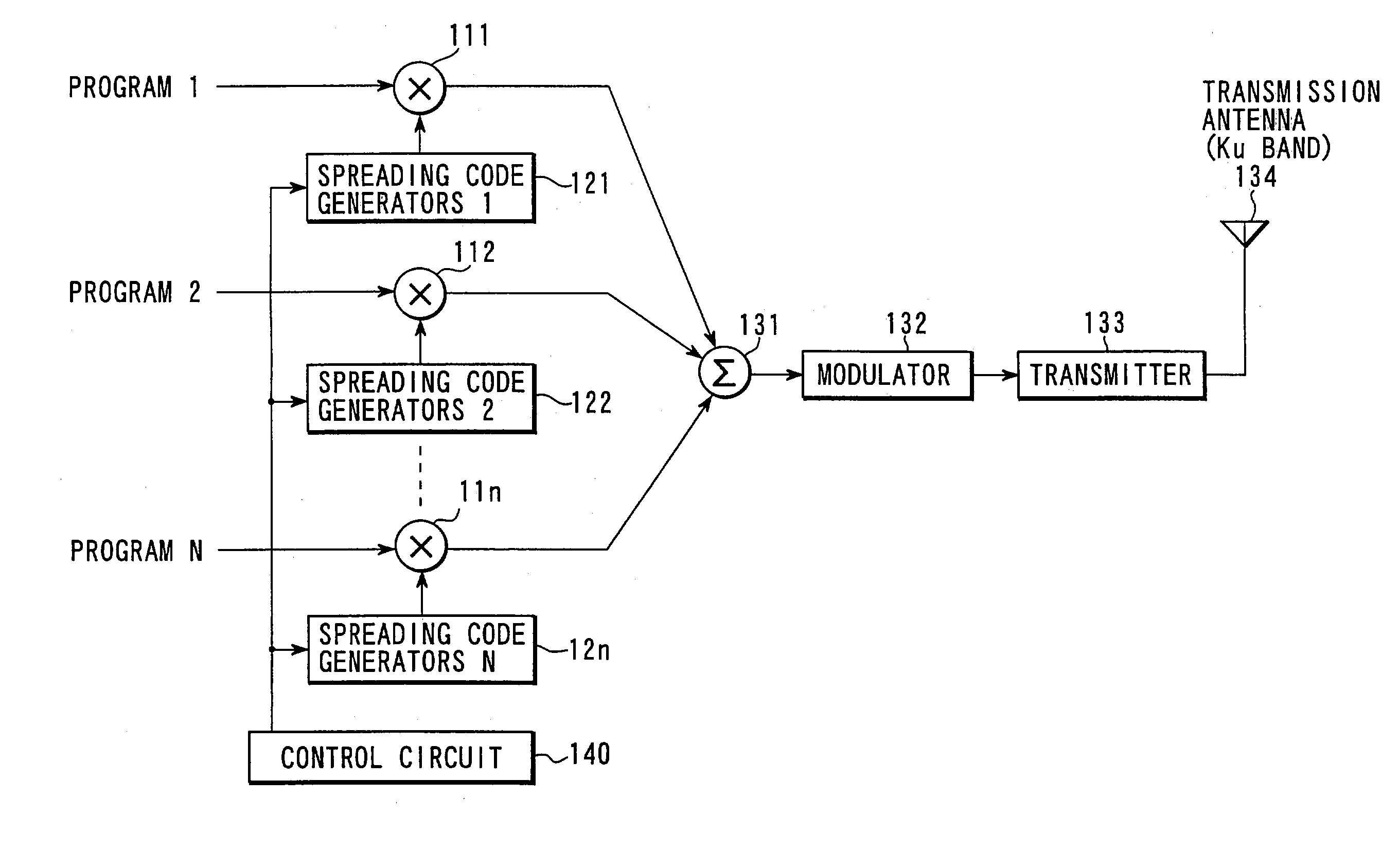
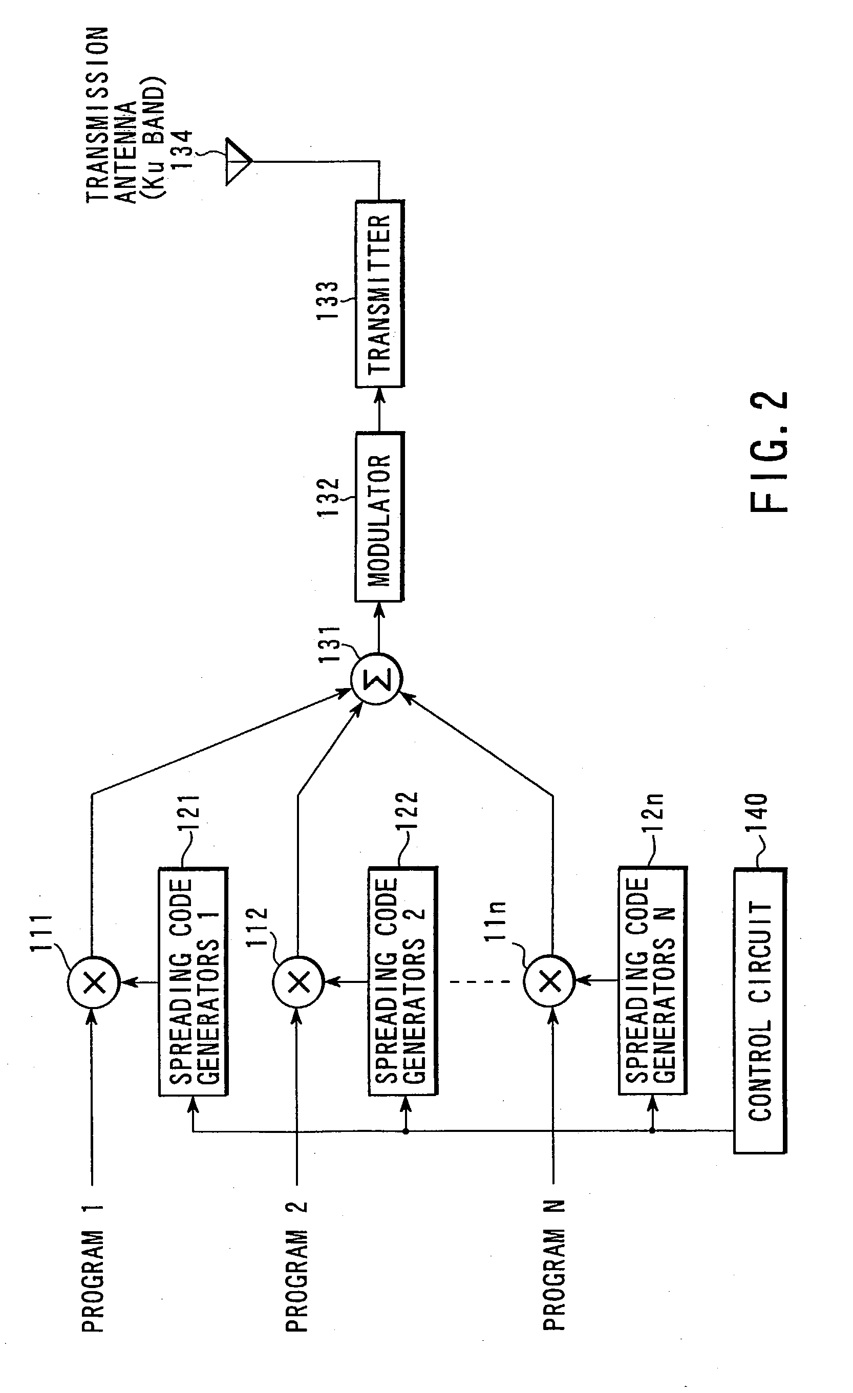
[0137] FIG. 4 is a block diagram showing the arrangement of the transmission section of each of the ground broadcasting stations BC1 and BC2 according to this embodiment. The same ...


PUM


Abstract

In a broadcasting receiver, to quickly switch channels of the received multiplexed broadcasting signals at a high response speed to improve the convenience for a viewer, when broadcasting signals of a plurality of channels are to be code-division-multiplexed and broadcasted from a ground broadcasting station (BC1, BC2) to a broadcasting receiver (MS) in a service area via a geostationary satellite (SAT), the broadcasting signals are multiplexed and transmitted after matching the spreading code phase between the channels in the ground broadcasting station (BC1, BC2). Alternatively, the spreading code phase difference between the channels of a CDM broadcasting signal arriving from the ground broadcasting station (BC1, BC2) is detected in the geostationary satellite (SAT), and the broadcasting signal is transmitted to the broadcasting receiver (MS) after matching the spreading code phase between the channels on the basis of the detection result.

Description

DESCRIPTIONSATELLITE BROADCASTING SYSTEM[0001] 1. Technical Field[0002] The present invention relates to a satellite broadcasting system for broadcasting information such as video, audio, and data to a specific ground service area using a broadcasting satellite or a communication satellite on the geostationary orbit and, more particularly, to a system for multiplexing and broadcasting a plurality. of channels by code division multiplex (CDM: Code Division Multiplex).[0003] 2. Background Art[0004] In recent years, various communication systems have been developed along with an increase in requirements for communications and progress in communication technologies. One of such communication systems is a satellite broadcasting system using a broadcasting satellite or a communication satellite on the geostationary orbit. The satellite broadcasting system has an advantage that it can provide an information broadcasting service to a wide service area without any large-scale infrastructure ...

Claims


Application Information

Patent Timeline
Patent Type & Authority Applications(United States)
IPC IPC(8): H04B7/185H04B1/711H04J13/10H04W84/06
CPCH04B7/18526H04B1/7075H04J13/16H04H20/51
Inventor SUENAGA, MASASHIOKA, MASARUKOISHI, YOICHIFUJIMORI, YUKIYOSHIKIKUCHI, HIDEO
Owner SUENAGA MASASHI
Why Eureka
Try Eureka