Optical module

a technology of optical fiber and optical fiber, applied in the field of optical fiber modules, can solve the problems of poor durability against light, limited light emitted by the light source used for pumping, and poor durability

Inactive Publication Date: 2003-07-31
FURUKAWA ELECTRIC CO LTD
View PDF3 Cites 45 Cited by
  • Summary
  • Abstract
  • Description
  • Claims
  • Application Information

AI Technical Summary

Problems solved by technology

However, the intensity of the light emitted from a semiconductor laser diode (LD) that is used for the light source for pumping has limitation.
In the meantime, the traditional optical fiber module having the circuit configuration shown in FIG. 29 and having the planar lightwave circuit component 30 connected to the optical fiber arrays 1 (1a and 1b) with an adhesive has had a problem that the durability against light is not excellent.
The adhesive deterioration has the deterioration due to the light that the adhesive absorbs high intensity light, and the deterioration due to temperature rise that is caused by the adhesive having absorbed the light.
Consequently, the insertion loss of the optical fiber module increased as large as about one decibel due to the light transmission for 1000 hours.
However, the optical fiber module having the connection configuration as shown in FIGS. 30 and 31 has had problems that it has a complex configuration more than that of the optical fiber module having the planar lightwave circuit component 30 connected to the optical fiber array with the adhesive and the price is high.
If so, the optical fiber module becomes expensive more and more, and the yield becomes low.
However, when the number of multiplexed wavelengths is greater, the light intensity after multiplexed is greater and the adhesive deterioration due to light becomes a problem.
However, when the planar lightwave circuit component 30 with the arrayed waveguide grating circuit is connected to the optical fiber array 1 disposed with the optical fibers 7 with the adhesive in the traditional manner, the adhesive is deteriorated.
In addition, since the arrayed waveguide grating circuit is large, it is significantly difficult to adapt the connection configuration shown in FIG. 30 to connecting the planar lightwave circuit component 30 with the arrayed waveguide grating circuit to the optical fiber array 1.
On this account, it has a problem of increasing the connection loss due to fabrication variations in the optical fiber array 1, thus having s...

Method used


Image

  • Optical module
  • Optical module
  • Optical module

Examples


first embodiment

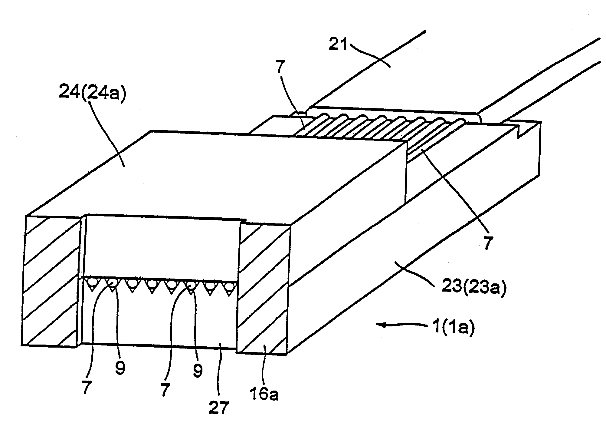
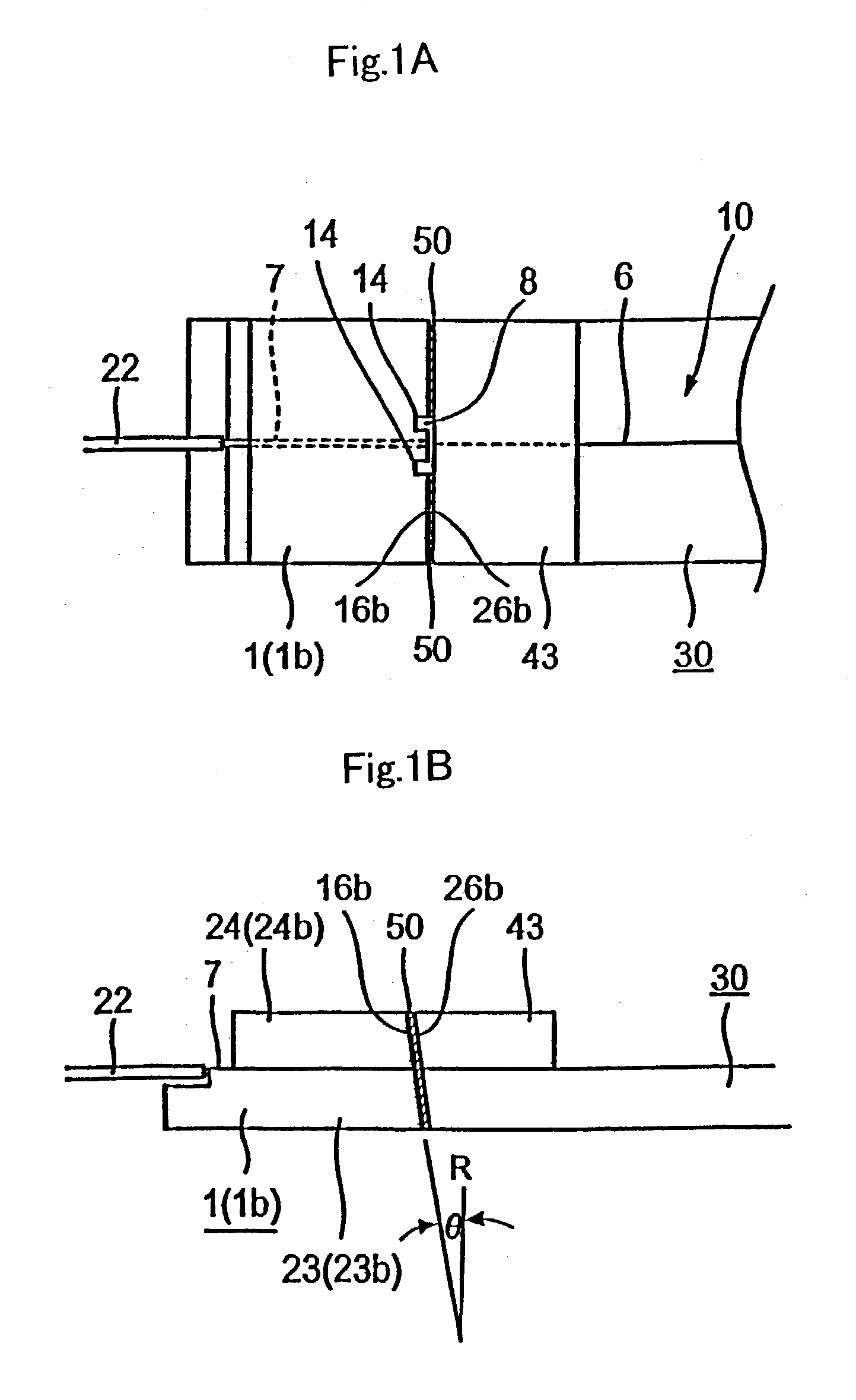
[0149] Furthermore, FIGS. 1A and 1B do not show the detailed configuration of a planar lightwave circuit 10 of the planar lightwave circuit component 30. However, in the optical fiber module of the first embodiment, the planar lightwave circuit component 30 has the planar lightwave circuit 10 of a straight waveguide, which is formed straight from the optical input end to the optical output end. The left end sides in FIGS. 1A and 1B are the output side of the optical fiber module. A single output optical waveguide 6 formed in the planar lightwave circuit component 30 is connected to an optical fiber 7 of the optical fiber array 1 (1b).

[0150] Moreover, not shown in FIGS. 1A and 1B, the input side of the optical fiber module of the first embodiment has the same configuration of the output side.

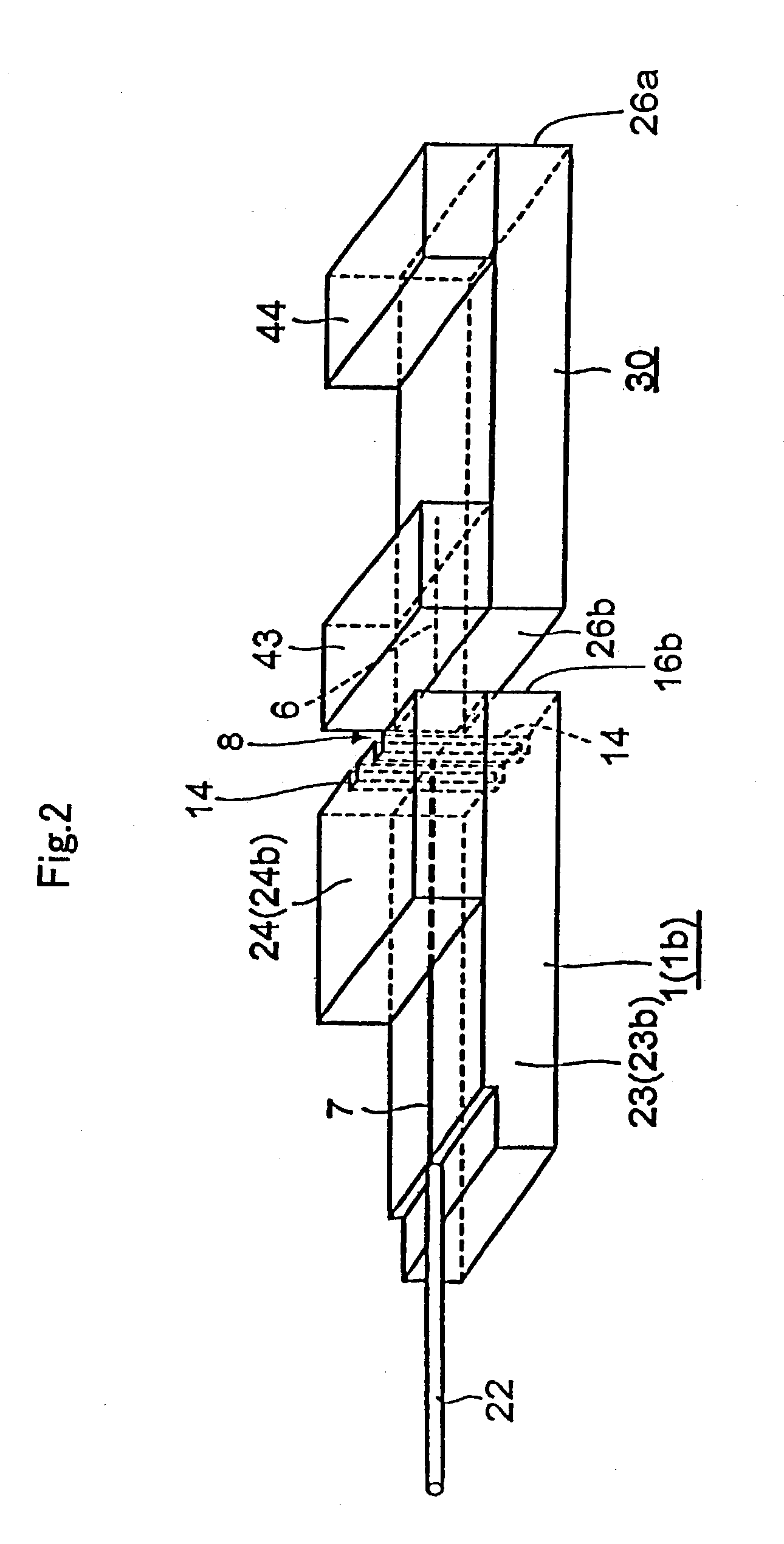
[0151] FIG. 2 illustrates the planar lightwave circuit component 30 and the optical fiber array 1 (1b) in the state before connected. Also in FIG. 2, the circuit configuration of the planar light...

second embodiment

[0184] In the optical fiber module of the second embodiment, the planar lightwave circuit component 30 has a planar lightwave circuit 10 that the number of stages of the Mach-Zehnder interferometer circuits 15 is one stage greater than that of the circuit connecting the Mach-Zehnder interferometer circuits 15 in multiple stages shown in FIG. 29.

[0185] FIG. 7 omits the detailed configuration of the planar lightwave circuit 10. However, the planar lightwave circuit component 30 adapted to the second embodiment has a circuit in which the Mach-Zehnder interferometer circuits 15 are connected to the separate input optical waveguides 2 shown in FIG. 29 and the light of eight wavelengths different from each other can be multiplexed.

[0186] In the optical fiber module of the second embodiment, the configuration of connecting the planar lightwave circuit component 30 to the optical fiber array 1 (1b) is the same as that of the first embodiment.

[0187] In addition, in the optical fiber module o...


PUM


Abstract

An optical fiber module of the invention is an optical fiber module easily fabricated and excellent in the characteristics of enduring high intensity light, for example. The connection end face of an optical fiber array as an optical component is faced to the connection end face of a planar lightwave circuit component. An optical fiber array is also disposed on the connection end face of the planar lightwave circuit component opposite to the optical fiber array. The corresponding connection end faces are connected to each other with an adhesive. A no adhesive filled part where the adhesive is not applied in the light transmitting area is disposed in at least one of bonding parts thereof.

Description

[0001] 1. Field of the Invention[0002] The present invention relates to an optical fiber module.[0003] 2. Discussion of the Background[0004] At present, the practical application of a planar lightwave circuit (PLC) component is proceeding in the field of optical communications. This planar lightwave circuit component is configured in which a planar lightwave circuit is formed on a silicon substrate or silica substrate, having advantages to realize low price and large scale integration. In addition, with the realization of forming the planar lightwave circuit component into a multi-function product, the large scale integration of the planar lightwave circuit to be arranged and upsizing of the planar lightwave circuit component are proceeding.[0005] Generally, the planar lightwave circuit component is connected to an optical fiber array having optical fibers arranged, and then it is formed into a module. An optical fiber module having the planar lightwave circuit component and the opt...

Claims


Application Information

Patent Timeline
IPC IPC(8): G02B6/125G02B6/30G02B6/34
CPCG02B6/12009G02B6/30G02B6/125
Inventor SAITO, TSUNETOSHIHASEGAWA, JUNICHITANAKA, KANJIKASHIHARA, KAZUHISA
Owner FURUKAWA ELECTRIC CO LTD
Why Eureka
Try Eureka