Battery

a battery and insulating sleeve technology, applied in the field of batteries, can solve the problems of void generation, deformation of air tightness of the battery sheath, and inability to completely prevent cracks in the ceramic insulating sleeve, so as to prevent cracks, reduce voids, and improve the strength of brazing

Inactive Publication Date: 2003-07-31
GS YUASA INT LTD
View PDF0 Cites 63 Cited by
  • Summary
  • Abstract
  • Description
  • Claims
  • Application Information

AI Technical Summary

Benefits of technology

[0020] According to the arrangement, the metallic terminal and the insulating sleeve made of ceramic are fixed to each other via the metallic ring. Therefore, even if when the temperature varies, a dimension of the gap between the terminal and the insulating sleeve changes to cause a distortion due to the difference in coefficient of thermal expansion between metal and ceramic, the distortion can be accommodated by the metallic ring being deflected. Thus, a crack can be prevented from occurring in the insulating sleeve with reliability.
[0035] Thus, the battery can have a more compact terminal structure.

Problems solved by technology

Accordingly, a battery, such as a non-aqueous electrolyte secondary battery, having such a conventional ceramic hermetic seal structure has a problem in that a distortion may occur between the positive terminal 4 or negative terminal 5 and the insulating sleeve 6 due to a variation of temperature, and the distortion stress may be concentrated in the insulating sleeve 6 to cause a crack in the ceramic material, resulting in a degradation of air tightness of the battery sheath.
However, such an arrangement could not completely prevent a crack from occurring in the ceramic insulating sleeve 6.
A detailed research concerning why the crack occurs in the brazing material has proved that, when the brazing material applied to the terminal is cooled, a void is produced in the brazing material due to volumetric shrinkage of the brazing material, and the void causes occurrence of a crack.
If a crack exists in the brazing material, a problem may arise in that the crack develops to pierce through the brazing material, thereby degrading air tightness of the battery sheath.
In such a case, there is an additional problem in that water is introduced into the battery and reacts with an active material (lithium if the battery is a lithium secondary battery, for example) to reduce the battery capacity or increase the internal resistance of the battery, which leads to decrease of the life of the battery.
This decreases the possibility that the brazing material is corroded, because the metallic ring is fixed to the outside of the battery sheath and the possibility that the brazing on the metallic ring is brought into contact with the electrolyte.

Method used


Image

  • Battery
  • Battery
  • Battery

Examples


first embodiment

[0056] [First Embodiment]

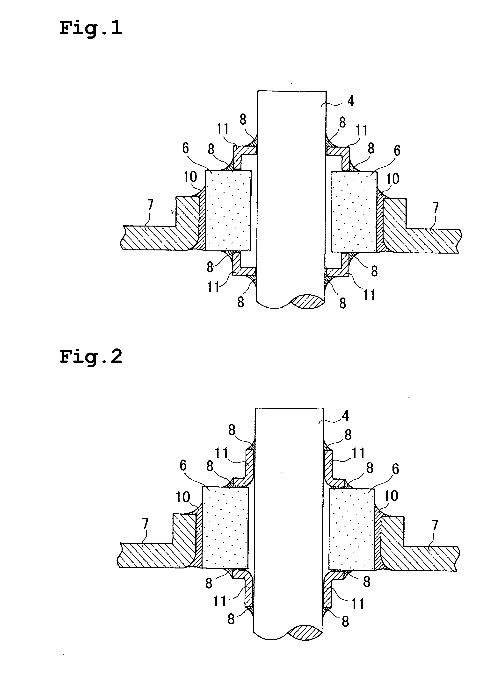
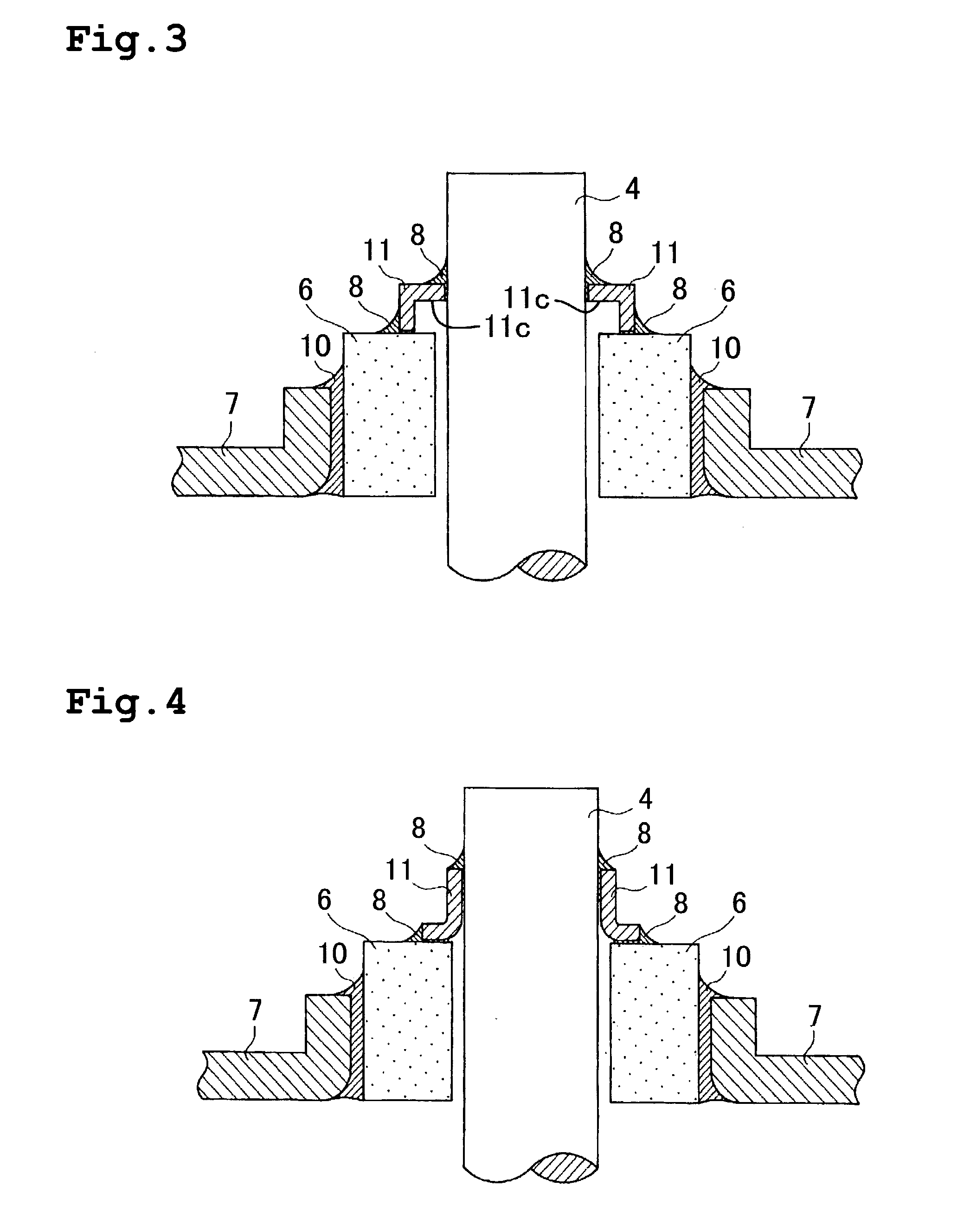
[0057] A first embodiment of the invention will be described with reference to FIGS. 1 to 4.

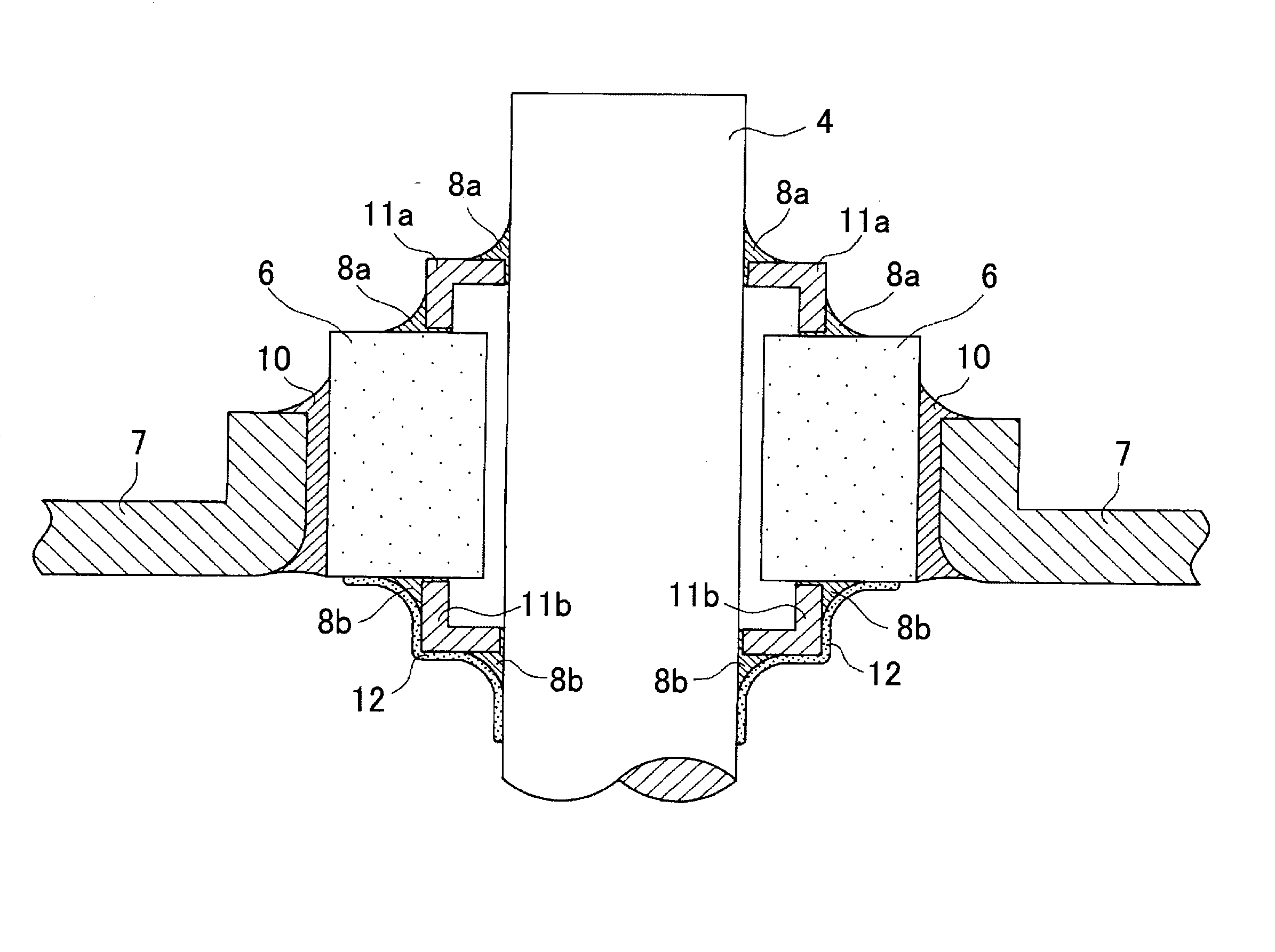
[0058] An insulating seal (ceramic hermetic seal) arrangement for a positive terminal 4 or negative terminal 5 according to this embodiment is used for a non-aqueous electrolyte secondary battery similar to the conventional battery described above.

[0059] The sheath of the non-aqueous electrolyte secondary battery is essentially the same as that of the conventional battery shown in FIG. 17, and thus, it is not illustrated. Referring to FIG. 17, it comprises an elliptic-cylindrical metallic case 2, a lid plate 3 that is hermetically fixed to the metallic case 2 in such a manner that it is fitted into an upper opening of the metallic case 2 and welded thereto, and terminal supporting plates 7, 7 that are hermetically fixed to the lid plate 3 in such a manner that they are fitted into openings in the lid plate 3 and welded thereto. The positive terminal 4 is hermetically ...

second embodiment

[0080] [Second Embodiment]

[0081] Now, a second embodiment of the invention will be described with reference to FIGS. 5 and 6. The same components as in the first embodiment are assigned the same reference numerals and any overlap of description thereof will be avoided. Differences between the embodiments will be described.

[0082] In general, ceramics used for the insulating sleeve 6 are characterized by the lower tensile strength and the higher resistance to compression force.

[0083] In the conventional arrangement shown in FIG. 19, for example, when the negative terminal 5 that has been thermally expanded is to be shrinked, the insulating sleeve 6 is subject to a tensile load, and a crack occurs in the insulating sleeve 6.

[0084] According to this embodiment, as shown in the example of the positive terminal 4 in FIG. 5, the metallic ring 11 is formed by bending downwardly the outer edge of a toroidal metallic plate so as to accommodate the upper end of the insulating sleeve 6 therein....

third embodiment

[0086] [Third Embodiment]

[0087] Now, a third embodiment of the invention will be described with reference to FIGS. 7 and 8. The same components as in the first embodiment are assigned the same reference numerals and any overlap of description thereof will be avoided. Differences between the embodiments will be described.

[0088] According to this embodiment, a metallic ring portion 4a is used as shown in FIG. 7, instead of the metallic ring 11 fitted over the positive terminal 4. The metallic ring 4a is formed by bending downwardly the outer edge of a circular flange extending from the outer surface of the positive terminal 4, and is L-shaped in cross section as in the case with the metallic ring 11 in the first embodiment. Thus, even if, when the temperature varies, a dimension of the gap between the positive terminal 4 and the insulating sleeve 6 changes to cause a distortion due to the difference in coefficient of thermal expansion between the aluminum alloy or the like and ceramic...


PUM

PropertyMeasurementUnit
insulatingaaaaaaaaaa
metallicaaaaaaaaaa
corrosion resistanceaaaaaaaaaa

Abstract

An insulating sleeve 6 made of ceramic hermetically fixed into an opening in a terminal supporting plate 7 in a battery sheath made of metal, a positive terminal 4 made of an aluminum alloy or negative terminal 5 made of a copper alloy is inserted in the insulating sleeve, and a metallic ring is fitted over the positive terminal 4 or negative terminal 5. The inner edge of the metallic ring 11 and the positive terminal 4 or negative terminal 5 are hermetically fixed to each other by an aluminum-based brazing metal 8 or copper-based brazing metal 9, and the outer edge of the metallic ring 11 and the insulating sleeve 6 are hermetically fixed to each other by an aluminum-based brazing metal 8 or copper-based brazing metal 9.

Description

[0001] 1. Field of the Invention[0002] The present invention relates to a battery having a terminal and a ceramic insulating sleeve.[0003] 2. Description of the Prior Art[0004] FIG. 17 shows an example of a structure of a conventional ceramic hermetic seal for a non-aqueous electrolyte secondary battery. The non-aqueous electrolyte secondary battery comprises a winding type of elliptic-cylindrical electric power generating element 1, an elliptic-cylindrical metallic case 2 that houses the electric power generating element 1, and an elliptic lid plate 3 that is hermetically fixed to the metallic case 2 in such a manner that it is fitted into an upper opening of the metallic case 2 and welded thereto.[0005] A positive terminal 4 and a negative terminal 5 connected to a positive electrode and a negative electrode, respectively, of the electric power generating element 1 each have a terminal supporting plate 7 attached thereto via an insulating sleeve 6 made of ceramic.[0006] As shown i...

Claims


Application Information

Patent Timeline
Patent Type & Authority Applications(United States)
IPC IPC(8): H01M10/04H01M50/179H01M50/559H01M50/562
CPCH01M2/06H01M10/0431H01M2/30Y02E60/10Y02P70/50H01M50/562H01M50/179H01M50/559
Inventor YOSHIDA, HIROAKIINOUE, TAKEFUMIIMAMURA, NOBUTAKAIWAMOTO, TATSUYANAOI, TAROMIYANAGA, NAOZUMIHATANAKA, TERUHIROSASHIKI, MASARUKAMATA, KOUJIYAMAZAKI, HIDEKI
Owner GS YUASA INT LTD
Why Eureka
Try Eureka