Method and apparatus for shunting induced currents in an electrical lead

a technology of induced current and electrical lead, which is applied in the direction of internal electrodes, transvascular endocardial electrodes, therapy, etc., can solve the problems of vastly more sophisticated and complex implantable medical devices, and insufficient operation of previously implanted leads

Inactive Publication Date: 2003-07-31
MEDTRONIC INC
View PDF13 Cites 144 Cited by
  • Summary
  • Abstract
  • Description
  • Claims
  • Application Information

AI Technical Summary

Problems solved by technology

Today's state-of-the-art implantable medical devices are vastly more sophisticated and complex than their early counterparts, and are capable of performing significantly more complex tasks.
For example, the previously implanted lead may have become insufficient in its operation and, thus, a new lead is needed.
In certain situations, such low-frequency current flow may result in undesirable stimulation of the body portion to which the lead extends or cause the electrical therapeutic and / or diagnostic device to malfunction, even though the abandoned lead is no longer attached to the device.
Traditionally, however, use of these technologies have been discouraged for patients having such implanted medical devices and / or abandoned leads, as the environment produced by the MRI or diathermy apparatuses is generally considered hostile to such implantable medical devices.
The dissipation of this electrical current may cause resistive heating in the tissue adjacent the electrode and may result in damage to the tissue in some cases.

Method used


Image

  • Method and apparatus for shunting induced currents in an electrical lead
  • Method and apparatus for shunting induced currents in an electrical lead
  • Method and apparatus for shunting induced currents in an electrical lead

Examples


first embodiment

[0039] FIG. 5 illustrates the electronic filter 402 (shown in FIG. 4). The electronic filter 402 comprises a capacitor 502 connected in series with the electrode 108 and a lead electrode 304 via the lead conductor 208. Generally, the capacitor 502 has higher impedance characteristics at lower current frequencies and lower impedance at higher current frequencies. The capacitance of the capacitor 502 is selected to provide a low impedance relative to the electrode-to-tissue impedance (ranging from about 20 ohms to about 100 ohms) at frequencies characteristic of currents induced by diagnostic and / or therapeutic energy producing equipment while providing a high impedance relative to the electrode-to-tissue impedance at frequencies characteristic of currents produced by pacing devices, neurostimulation devices, and the like. In this way, lower frequency currents are substantially prevented from flowing from the electrode 108 into the lead conductor 208, while higher frequency currents, ...

third embodiment

[0044] FIG. 7 illustrates the filter 402 (shown in FIG. 4). In this embodiment, the filter 402 includes a capacitor 702 and an LC network 704 connected in series between the lead electrode 304 and the electrode 108. In the illustrated embodiment, the LC network 704 is constructed using a thin wire 706 with thin insulation that, when wound into a coil 708, uses the self-capacitance (illustrated by capacitors 710) and the inductance of the coil 708 to form a resonant circuit. In one embodiment, the LC network 704 self-resonates at a frequency of about 32 MHz and the capacitor 702 provides a low impedance at a frequency of about 64 MHz. Thus, currents having frequencies of about 32 MHz (the resonant frequency of the LC network 704) are impeded from being emitted from the lead electrode 304, while currents having frequencies of about 64 MHz are allowed to flow from the electrode 108 and, to a lesser extent, from the lead electrode 304. In leads (such as the lead 104 or the like) that ha...


PUM


Abstract

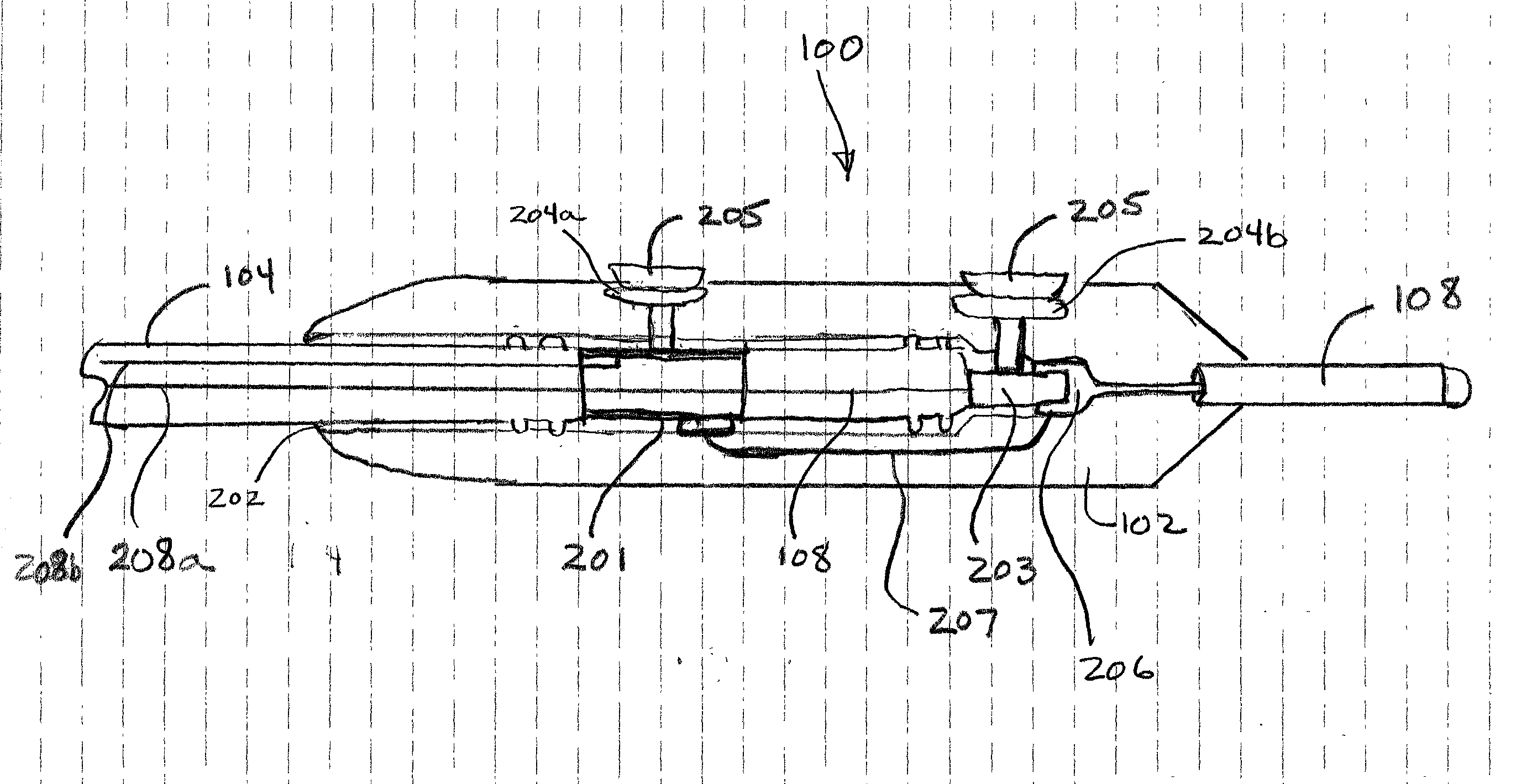
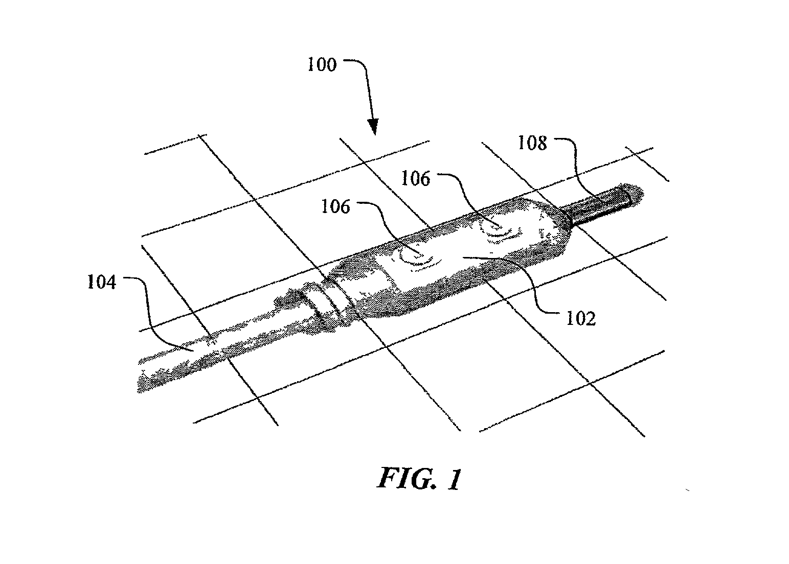
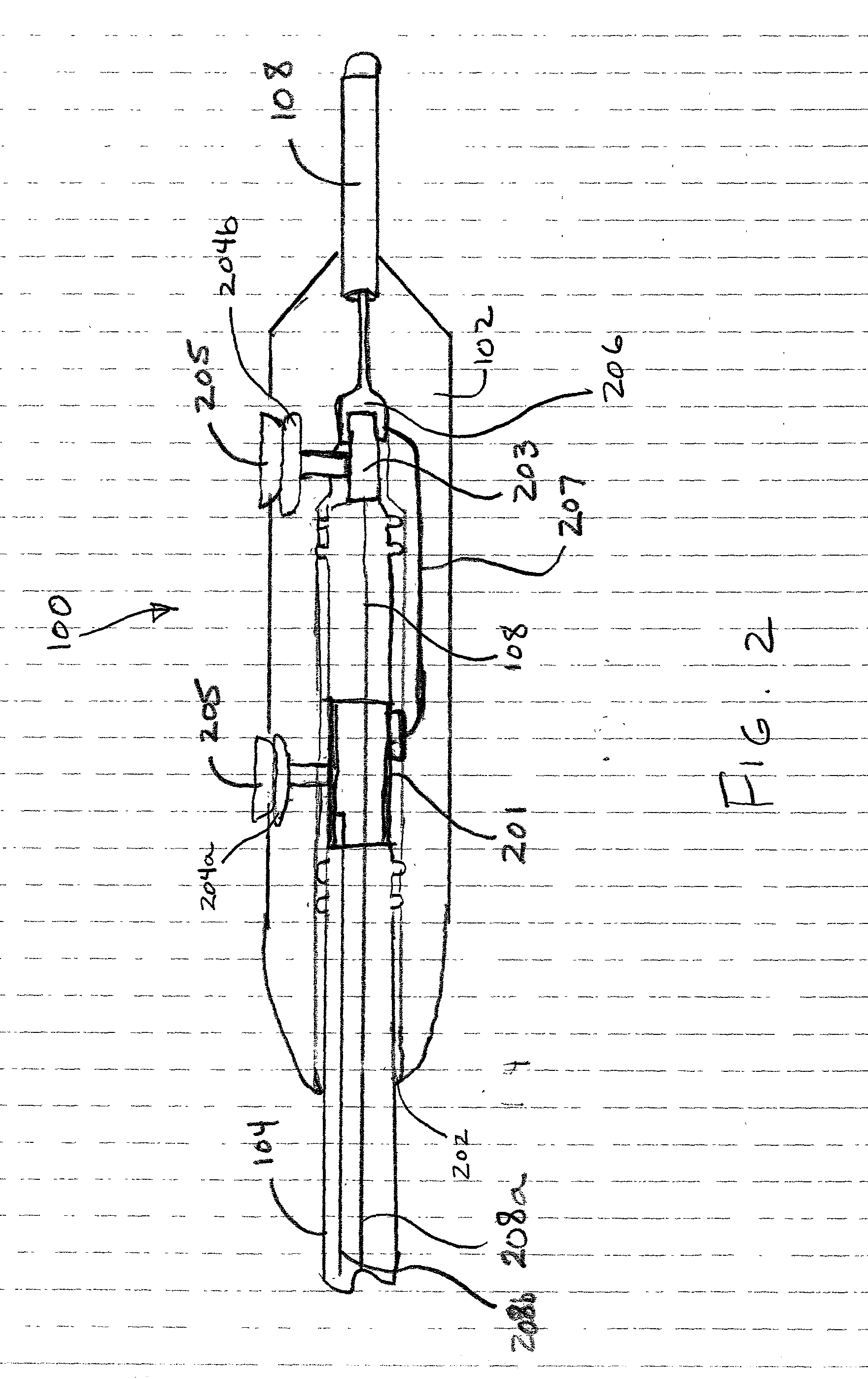
An electrical lead end cap includes a body defining a bore therein capable of receiving and retaining an end of an electrical lead and a connector capable of electrically coupling conductors leading to at least two electrodes. A method includes routing an electrical current induced in an electrical lead conductor disposed within body tissue to a plurality of electrodes, electrically coupled with the body tissue, via a circuit within an end cap attached to the electrical lead.

Description

[0001] This invention generally relates to implantable medical devices and, more specifically, to a method and apparatus for shunting electrical currents induced in an abandoned electrical lead.DESCRIPTION OF THE RELATED ART[0002] Since the introduction of the first implantable pacemakers in the 1960s, there have been considerable advancements in both the fields of electronics and medicine, such that there is presently a wide assortment of commercially available body-implantable electronic medical devices. The class of implantable medical devices now includes therapeutic and diagnostic devices, such as pacemakers, cardioverters, defibrillators, neural stimulators, and drug administering devices, among others. Today's state-of-the-art implantable medical devices are vastly more sophisticated and complex than their early counterparts, and are capable of performing significantly more complex tasks. The therapeutic benefits of such devices have been well proven.[0003] Modern electrical ...

Claims


Application Information

Patent Timeline
Patent Type & Authority Applications(United States)
IPC IPC(8): A61N1/05
CPCA61N1/056A61N2001/086A61N1/3718A61N1/086
Inventor REINKE, JAMES D.WILKINSON, JEFFREY D.KALIN, RONFOERSTER, LAURIE D.ZEIJLEMAKER, VOLKERT A.
Owner MEDTRONIC INC
Why Eureka
Try Eureka