Cleaning equipment for the cleaning of tanks

Inactive Publication Date: 2003-08-07
ALFA LAVAL TANK EQUIP
View PDF5 Cites 25 Cited by
  • Summary
  • Abstract
  • Description
  • Claims
  • Application Information

AI Technical Summary

Benefits of technology

0013] Moreover, a saving in cleaning fluid is effected, in that the outside of the pipe is flushed clean by a combination of a cleaning jet and a film of fluid which transports the impurities away. The fluid film will soften possible deposits, while the cleaning jet will detach the deposits which are thereafter transported away by the down-seeping fluid.
0014] As disclosed in claim 3, by configuring the channel in the housing with decreasing cross-section towards the outlet opening, a nozzle effect i

Problems solved by technology

In many cases this cleaning is insufficient.
First and foremost, the cleaning equipment extending into the tank, such as a cleaning boom with nozzles and the chamber with supply pipes, is in itself a problem, the reason being that there are parts which are unable to be sprayed, and herewith that there are areas which are not effectively cleaned.
To this can be added t

Method used


Image

  • Cleaning equipment for the cleaning of tanks
  • Cleaning equipment for the cleaning of tanks
  • Cleaning equipment for the cleaning of tanks

Examples


Embodiment Construction

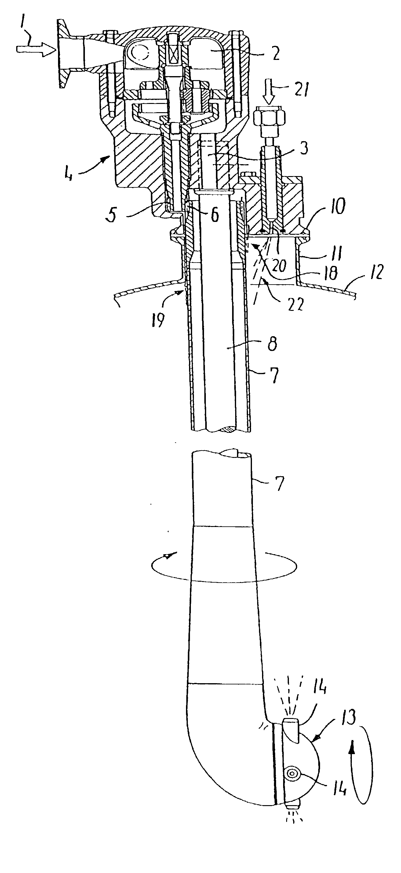
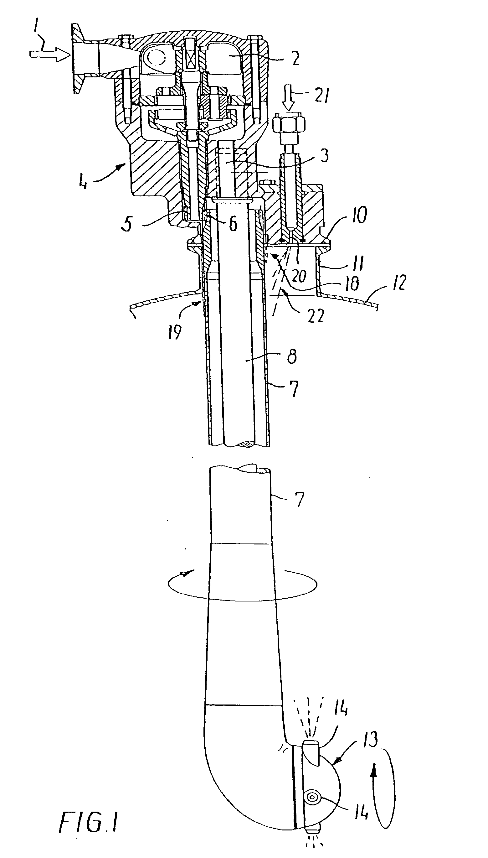
[0020] In FIG. 1 there is seen an example of an embodiment of the equipment mounted on a tank 12 with a mounting stub 11 with a flange 10.

[0021] The cleaning equipment itself is mounted on this stub 11 and the flange 10.

[0022] This equipment comprises a housing 4 with an inlet 1 for cleaning fluid under pressure, said fluid being led towards a turbine / blade wheel 2 in a hydraulic motor, which via a planetary gear turns a drive shaft 5 with external teeth on the lower part.

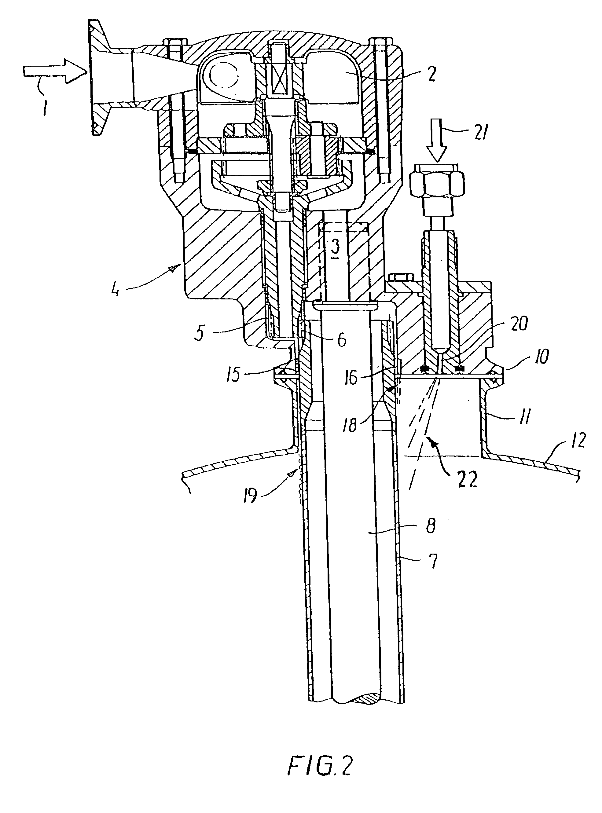
[0023] These teeth are in engagement with a gear ring 6 on a pipe 7 which is suspended in a bush 15, see FIG. 2, in the housing 4.

[0024] The bearing bush 15 is crimped to the pipe 7 or secured hereto in another manner.

[0025] Inside the pipe 7 there extends a fixed stay 8 which supports the rotating head 13 at its lower end, said head being provided with a number of nozzles 14 which, as indicated in FIG. 1, extend in a plane which is substantially parallel with the stay 8.

[0026] Between the pipe 7 and the rotating h...


PUM


Abstract

Within the foodstuffs, the pharmaceutical and corresponding industries, it is of the utmost importance that the insides of tanks and the equipment existing herein can be held completely clean without the risk of undesired bacterial growth, cross-contamination etc. Equipment for the cleaning of tanks comprises a submerged pipe with a nozzle head mounted on the bottom, through which nozzles cleaning fluid is sprayed from below and upwards, while at the same time the nozzles are rotated and turned around inside the tank. In order to ensure an effective cleaning of this submerged equipment, according to the invention this equipment is configured so that cleaning fluid is constantly led out over the pipe (7) which extends down into the tank. This leading-out (18, 19, 22) is effected partly via a channel (17) in the bearing bush (15) for the pipe (7) in the housing (4) for the formation of a film of fluid (19) on the pipe (7), and partly via a channel (16) or a separate nozzle (20) in the housing (4) for the formation of a cleaning jet (18, 22) directed towards the pipe (7).

Description

THE KNOWN TECHNIQUE[0001] The invention concerns equipment for the cleaning of the inside of tanks and similar containers, said equipment being mounted on the top and comprising a motor in a housing in which there is suspended a pipe which extends into the tank and on which there is mounted a nozzle head, in that said motor rotates the pipe and the nozzle head at the same time that cleaning fluid is sprayed from one or more nozzles on the nozzle head towards the inside surfaces of the tank, while at the same time that cleaning fluid is applied to the pipe for the external cleaning of the pipe.[0002] Cleaning equipment of this kind is used for the cleaning of tanks when they are empty, and will be able to be configured in accordance with a programme which is pre-set from the point of view of timing as well as the choice of cleaning pattern.[0003] The equipment can be mounted either in a permanent manner or it can be mounted when taken into use.[0004] The actual cleaning consists of t...

Claims


Application Information

Patent Timeline
IPC IPC(8): B08B9/093
CPCB08B9/0936
Inventor JEPSEN, ERIK LUNDTHOGERSEN, KLAUSSIE, GUNNER MONRAD
Owner ALFA LAVAL TANK EQUIP
Why Eureka
Try Eureka