Soldering iron with heat pipe

a technology of heat pipe and iron, applied in the field of iron polishing, can solve the problems of high cost, high difficulty in precision work, and easy hotness of polishing iron, and achieve the effect of increasing the cos

Inactive Publication Date: 2003-08-07
HAKKO CO LTD
View PDF0 Cites 19 Cited by
  • Summary
  • Abstract
  • Description
  • Claims
  • Application Information

AI Technical Summary

Problems solved by technology

However, shortening the dimension between them leads to the situation such that the grip portion of the soldering iron gets easily hot, necessitating to halt the soldering work or to have a user wear a thick grove, which, in turn, makes the precision work highly difficult.
Or there is another way to cope with this situation, that is, to mount a thermal insulation type cover around the gr

Method used


Image

  • Soldering iron with heat pipe
  • Soldering iron with heat pipe
  • Soldering iron with heat pipe

Examples


Embodiment Construction

[0033] Hereinafter, a soldering iron 1 of the present invention is described with reference to the drawings.

[0034] General description of the structure of a soldering iron as one embodiment:

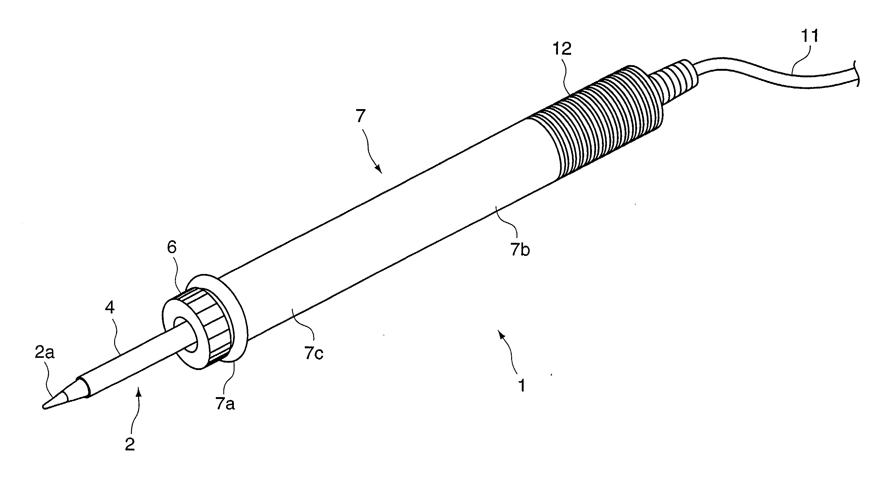
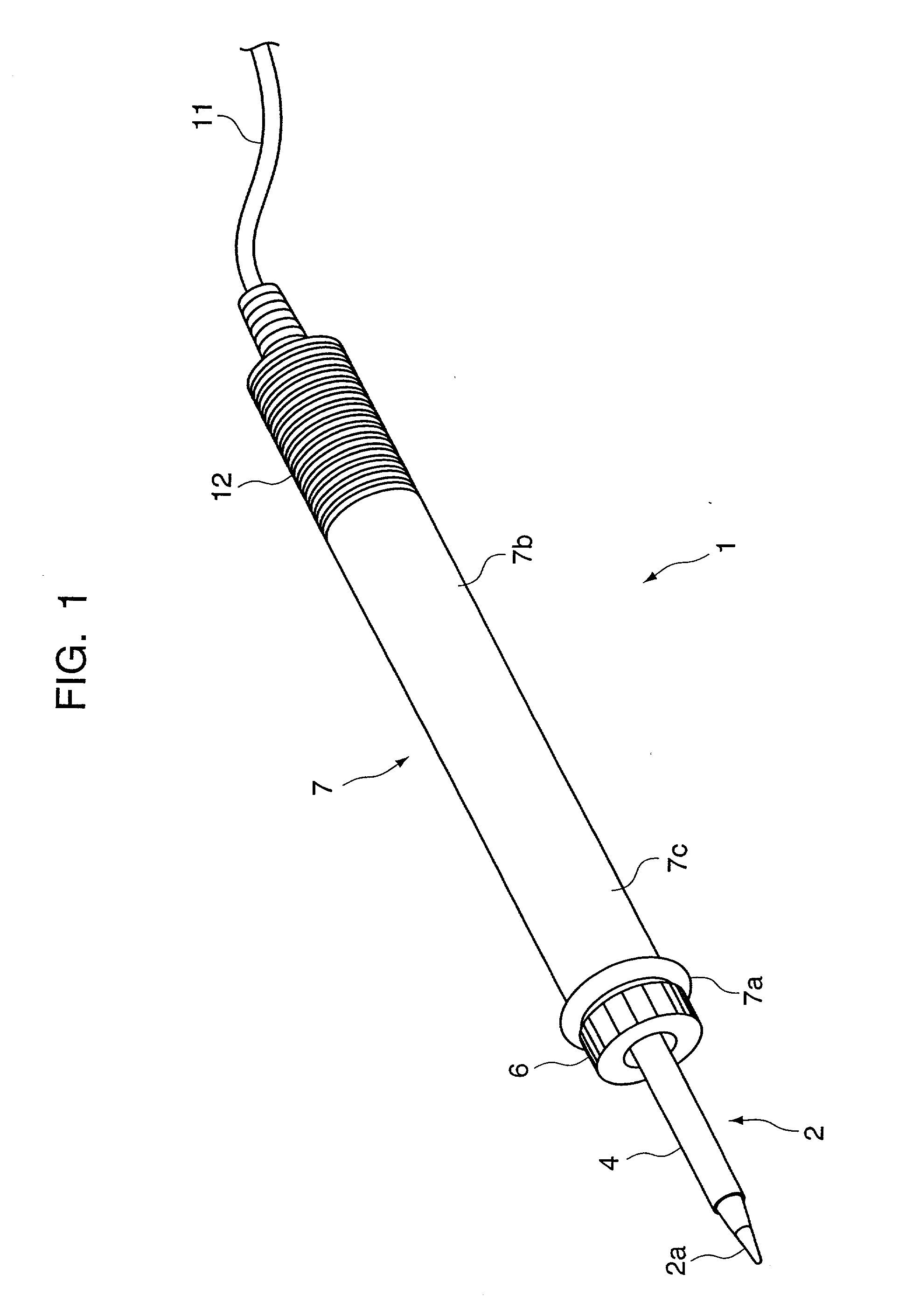
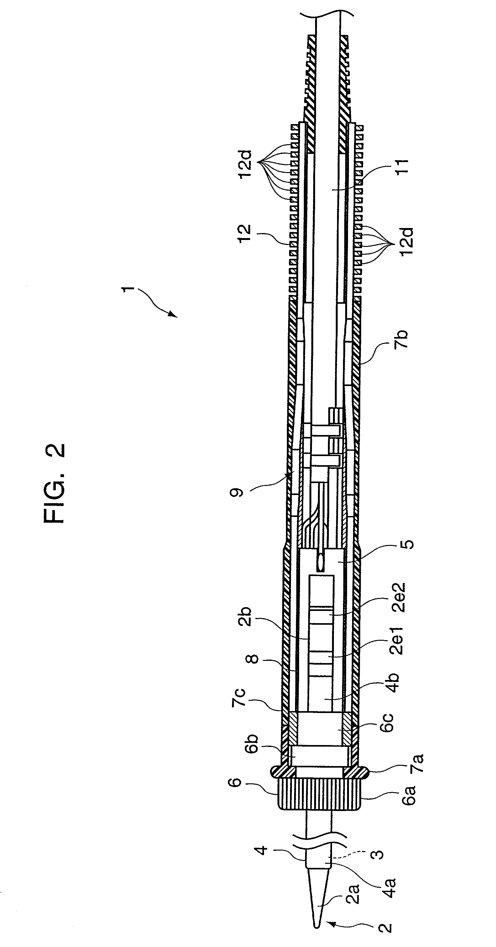
[0035] FIG. 1 is a perspective view showing an overall structure of a soldering iron 1 which equips a heat pipe 9 as one embodiment of the present invention. FIG. 2 is a diagram showing an interior structure of the soldering iron shown in FIG. 1.

[0036] The soldering iron 1 is formed with the following parts. A solder tip 2, composed of a tip end 2a and a rear portion 2b extending from the tip end 2a, a heater 3 provided in the solder tip 2, a protection pipe 4 which is in a form of hollow cylinder, extending from a front portion 4a to a rear portion 4b, encasing the medium portion of the solder tip 2 and the heater 3, and a nipple 6 which is securely placed onto the outer circumference of the protection pipe 4 to securely hold the solder tip 2 to a grip member 7. The grip member 7 is divided into...


PUM

PropertyMeasurementUnit
Shapeaaaaaaaaaa
Areaaaaaaaaaaa
Dimensionaaaaaaaaaa

Abstract

A soldering iron comprises a tip end; a heater portion for electrically heating the tip end of the soldering iron; a holding portion provided at the rear end of the heater portion: a heat pipe structure provided in the holding portion; a first heat pipe holder for holding a frontal portion of the heat pipe structure to which heat generated at the heater portion is transferred; a second heat pipe holder for holding a rear part of the heat pipe structure; and a grip portion placed externally around the first heat pipe holder.

Description

[0001] 1. Field of the Invention[0002] This invention relates to a soldering iron. More specifically this invention relates to a soldering iron including a solder tip and heater electrically heating the tip end.[0003] 2. Description of the Related Art[0004] In recent years, sizes of the parts and substrates on which soldering work needs to be performed have been getting smaller and thus the precision work has been on demand for soldering work. As a result, the dimension between the tip end and the grip portion was required to be shorter. However, shortening the dimension between them leads to the situation such that the grip portion of the soldering iron gets easily hot, necessitating to halt the soldering work or to have a user wear a thick grove, which, in turn, makes the precision work highly difficult. Or there is another way to cope with this situation, that is, to mount a thermal insulation type cover around the grip portion; however, doing so necessitates addition to the extr...

Claims


Application Information

Patent Timeline
IPC IPC(8): B23K3/02B23K3/03
CPCB23K3/027B23K3/0361B23K3/0338
Inventor MIYAZAKI, MITSUHIKO
Owner HAKKO CO LTD
Why Eureka
Try Eureka