Method for the reduction of combustion-driven oscillations in combustion systems and premixing burner for carrying out the method

Inactive Publication Date: 2003-08-14
ANSALDO ENERGIA IP UK LTD
View PDF4 Cites 21 Cited by
  • Summary
  • Abstract
  • Description
  • Claims
  • Application Information

AI Technical Summary

Benefits of technology

[0013] Advantageously, the fuel discharge takes place through at least one fuel nozzle orifice formed at the lance end, in such a way that the fuel discharged in the interior of the burner is mixed in a very finely distributed manner with inflow air and is at the same time swirled. In particular, due to the wake at the lance end, further stabilization of the aerodynamically generated backflow zone takes place. In particular, as a result of the fuel introduction according to the invention in a position shifted downstream within the burner interior, the flame forming within the backflow zone is prevented from periodically running out of the burner and running back into the latter. By the fuel discharge being in spatial proximity to the backflow zone forming within the combustion chamber, precisely that vortex breakdown can be assisted by the swirled fuel / air mixture spreading out in the flow direction, with the result that the backflow zone and consequently the flame are decisively stabilized.

Problems solved by technology

When turbomachines such as, for example, gas turbine plants are in operation, combustion-driven thermoacoustic oscillations often occur in the combustion chambers, these taking the form of fluidic instability waves at the burner and lead to flow vortices which greatly influence the entire combustion operation and lead to undesirable periodic heat releases within the combustion chamber.
This results in pressure fluctuations of high amplitude which may lead to undesirable effects, such as to a high mechanical load on the combustion chamber housing, to increased NO.sub.x emission as a result of inhomogeneous combustion or even to an extinguishing of the flame within the combustion chamber.
However, this method of reducing thermoacoustic oscillation amplitudes entails the disadvantage that the injection of fuel at the head stage is accompanied by an increase in the emission of NO.sub.x.
Investigations of the formation of thermoacoustic oscillations have shown that flow instabilities often lead to these instabilities.
Since this frequency coincides with typical fundamental characteristic modes of many annular burners in gas turbine plants, the thermoacoustic oscillations present a problem.

Method used


Image

  • Method for the reduction of combustion-driven oscillations in combustion systems and premixing burner for carrying out the method
  • Method for the reduction of combustion-driven oscillations in combustion systems and premixing burner for carrying out the method
  • Method for the reduction of combustion-driven oscillations in combustion systems and premixing burner for carrying out the method

Examples


Embodiment Construction

[0016] The invention will be described below by way of example, without the general idea of the invention being restricted, by means of exemplary embodiments, with reference to the drawings in which:

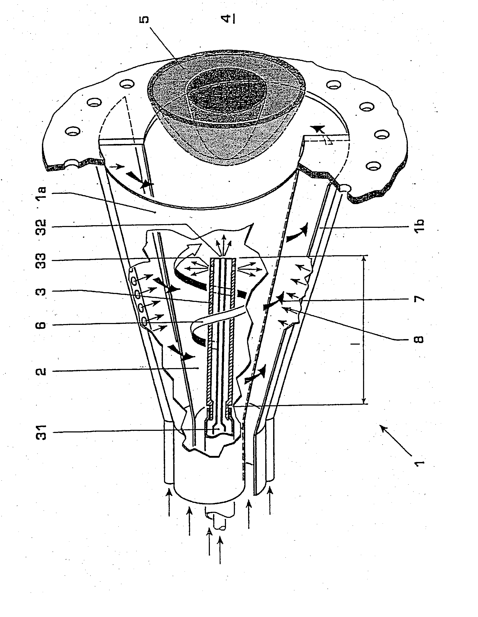
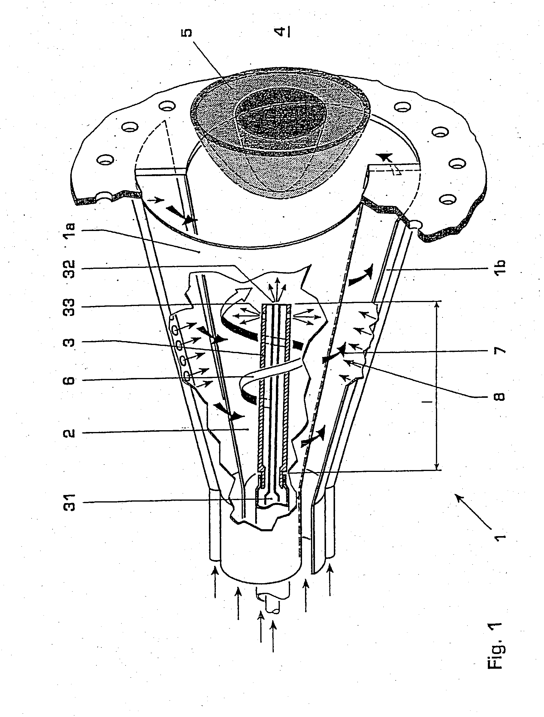
[0017] FIG. 1 shows a diagrammatic longitudinal section through a conically designed burner with a lengthened burner lance,

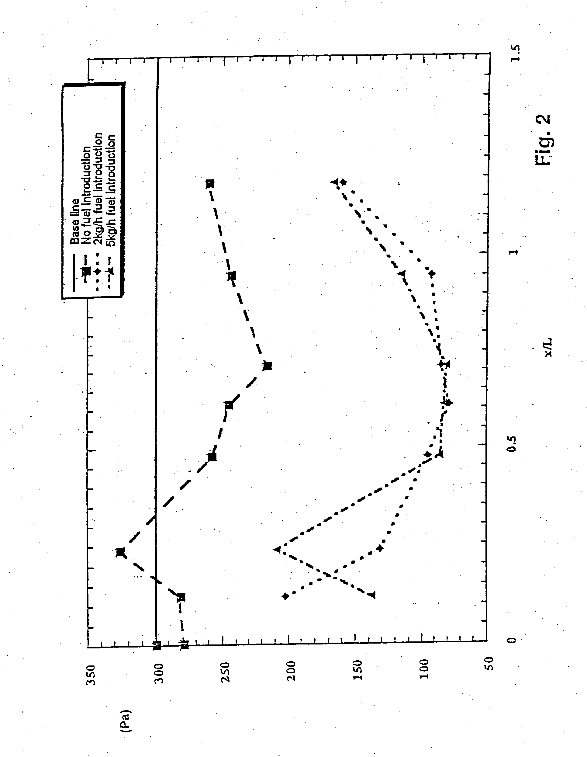
[0018] FIG. 2 shows a graphical illustration of the dependence of the length of the burner lance on the acoustic damping behavior,

[0019] FIG. 3 shows a graphical illustration of the dependence of the length of the burner lance on the acoustic damping behavior in terms of different lance configurations,

[0020] FIG. 4 shows a graphical illustration of the dependence of the length of the burner lance on the NO.sub.x emissions in terms of different lance configurations,

[0021] FIG. 5-8 show different burner lance configurations.

[0022] FIG. 1 illustrates in longitudinal section a premixing burner 1, such as may be gathered in terms of its basic construction, for example, fr...


PUM


Abstract

A method and a device are described for the controlled damping of combustion-driven oscillations in a turbomachine with a burner system providing at least one burner, into which is introduced, via at least one burner nozzle arranged centrally in the burner, fuel which is intermixed with combustion inflow air flowing into the burner, to form a fuel / air mixture which is ignited in a combustion chamber following the burner system. The invention is distinguished in that the fuel nozzle is designed in the form of a burner lance, at the lance end of which fuel discharge into the burner takes place, and in that the burner lance projects into the burner in the amount of at least one third of the axial burner length.

Description

[0001] The invention relates to a method for the reduction of combustion-driven oscillations in combustion systems, in particular in those with low acoustic damping, such as are often to be found in combustion chambers of turbomachines, and to a premixing burner for carrying out the method.PRIOR ART[0002] When turbomachines such as, for example, gas turbine plants are in operation, combustion-driven thermoacoustic oscillations often occur in the combustion chambers, these taking the form of fluidic instability waves at the burner and lead to flow vortices which greatly influence the entire combustion operation and lead to undesirable periodic heat releases within the combustion chamber. This results in pressure fluctuations of high amplitude which may lead to undesirable effects, such as to a high mechanical load on the combustion chamber housing, to increased NO.sub.x emission as a result of inhomogeneous combustion or even to an extinguishing of the flame within the combustion cha...

Claims


Application Information

Patent Timeline
IPC IPC(8): F23R3/18F23C7/00F23D11/40F23D14/74F23D17/00F23R3/12F23R3/28F23R3/30
CPCF23C7/002F23C2900/07002F23D11/402F23R2900/00014F23D17/002F23D2210/00F23R3/286F23D14/74
Inventor GUTMARK, EPHRAIMPASCHEREIT, CHRISTIAN OLIVER
Owner ANSALDO ENERGIA IP UK LTD
Why Eureka
Try Eureka