
Control system

A control system and control device technology, applied in the field of control systems, can solve problems such as battery exhaustion, small EEPROM capacity, and limited data volume

Inactive Publication Date: 2003-03-12
FUJITSU GENERAL LTD
View PDF0 Cites 16 Cited by
  • Summary
  • Abstract
  • Description
  • Claims
  • Application Information

AI Technical Summary

Problems solved by technology

[0010] In the above-mentioned conventional method, as the number of ECU configurations increases, the consumption current for storage and maintenance, that is, the dark current increases, and when the battery is transported or left idle, there is a possibility that the power of the battery is prematurely reduced. exhaustion problem
[0011] In addition, although it is possible to reduce the press current used for storage and retention as much as possible, as long as the basic structure of the ECU is not changed, the effect of this effort is very limited.
[0012] In addition, although the EEPROM of the non-volatile memory that can continue to hold data after the power supply is stopped can be configured in each ECU, and a part of the data stored in the RAM can be stored in the EEPROM, but because the capacity of the EEPROM is generally small , the amount of data that can be written is limited, and because the cost is increased if the capacity is increased, there is a problem that the usage is limited

Method used

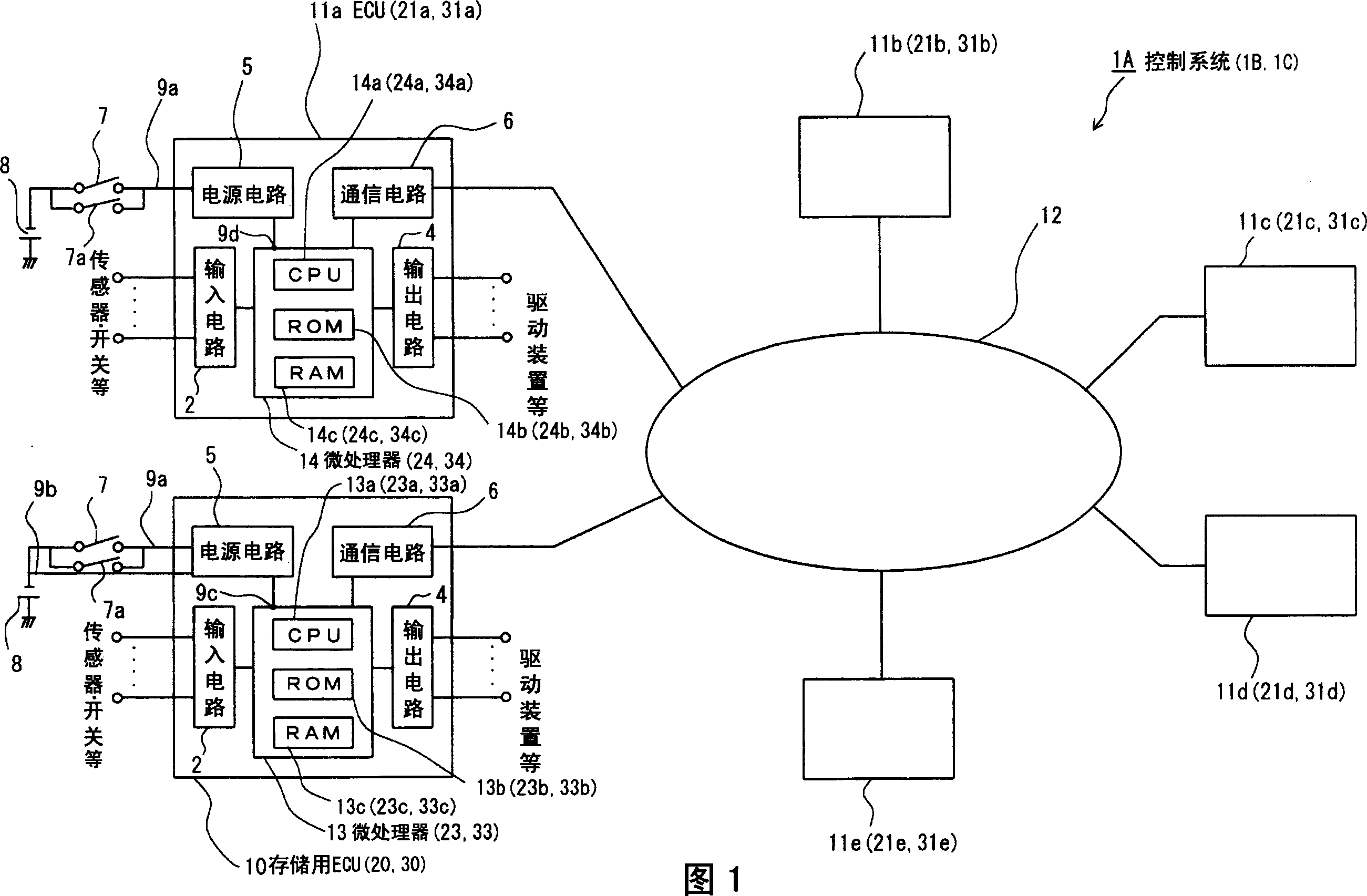
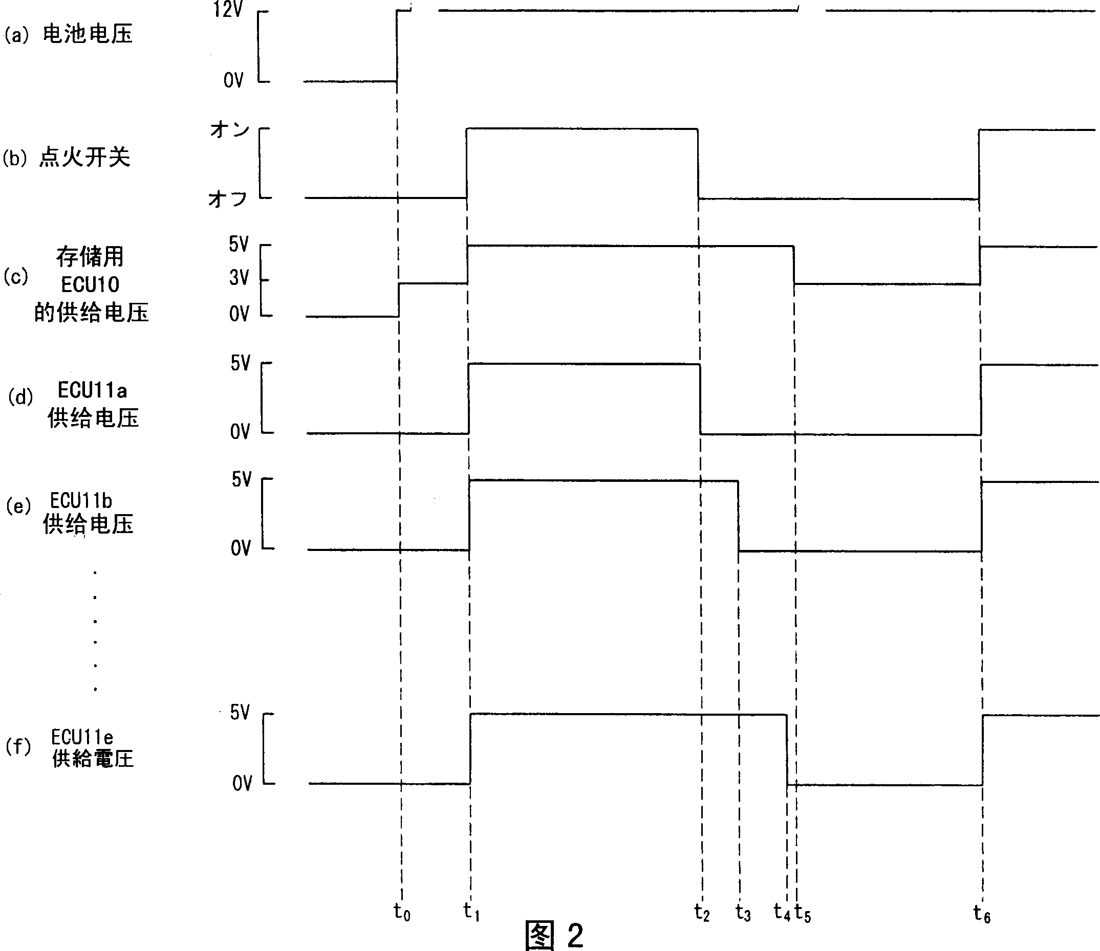
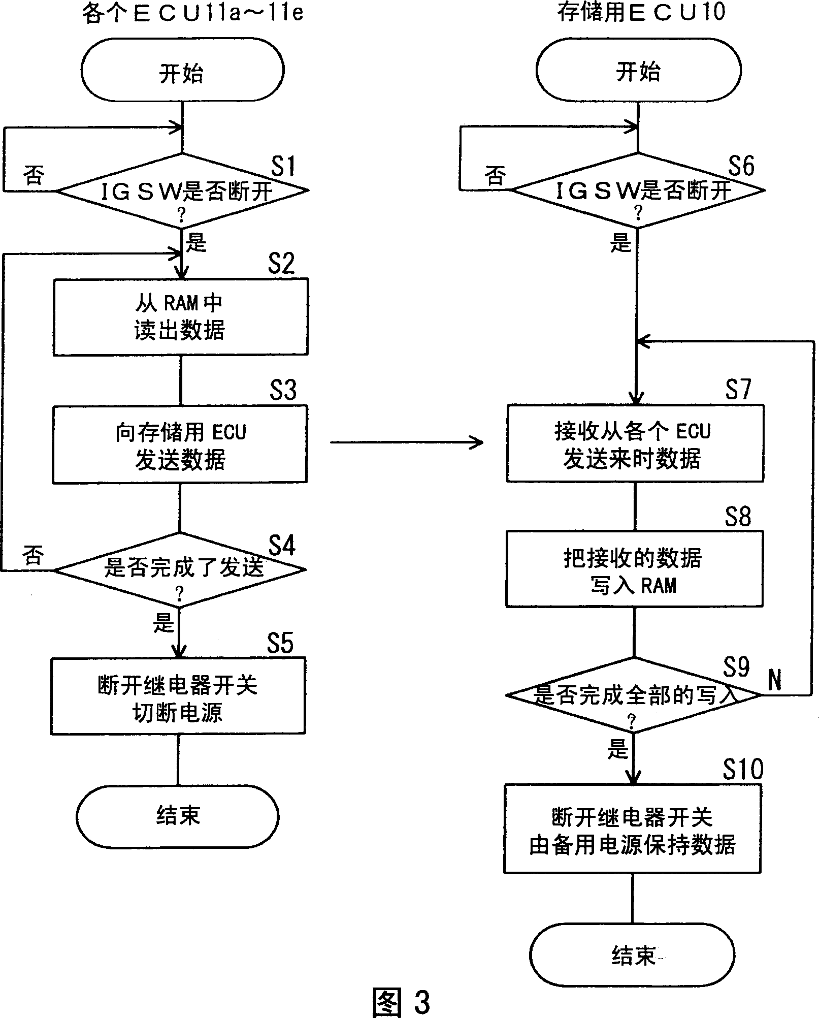

Image

  • Control system
  • Control system
  • Control system

Examples


Embodiment 2

[0100] The difference between the control system of Embodiment 2 and the control system of Embodiment 1 is that each ECU 21 a to 21 e sends the data stored in RAM 24 c, ... to the storage ECU 20 multiple times when the IGSW 7 is turned off. , the ECU 20 for storage receives the data sent multiple times, judges whether they are the same, and stores them in the RAM 23c when it is judged to be the same data.

[0101] Below, combine Figure 5 The flowchart shown in the embodiment 2 is for the data transmission processing action performed by the microprocessors 24, ... of the ECUs 21a to 21e and the microprocessor 20 of the storage ECU 20 when the IGSW7 of the control system of the second embodiment is switched from on to off. The data storage processing operation performed by the processor 23 will be described. In addition, the same processes as those in the control system of the first embodiment shown in FIG. 3 are denoted by the same symbols, and their descriptions are omitted....

Embodiment 3

[0115] The difference between the control system of the third embodiment and the control system of the first embodiment is that the transmission of the data stored in the RAM 34c, ... of the ECUs 31a to 31e to the storage ECU 30 is not only when the off state of the IGSW7 is detected. , and periodically during the on-state of IGSW7.

[0116] Below, combine Image 6 The flow chart shown in the control system of the third embodiment illustrates the data transmission processing action and storage performed by the microprocessors 34, ... of the ECUs 31a to 31e when the IGSW7 is switched from the on state to the off state. Data storage processing operation performed by the microprocessor 33 of the ECU 30 . In addition, the same processing as that in the control system of the first embodiment shown in FIG. 3 is denoted by the same reference numerals, and description thereof will be omitted.

[0117] In addition, since the processing operations of the respective ECUs 31a to 31e diffe...

Embodiment 5

[0156] The difference between the control system of Embodiment 5 and the control system of Embodiment 4 is that each ECU 51 a to 51 e judges whether the data read from the EEPROM 15 is consistent with the data sent from the storage ECU 50 when the IGSW 7 is turned on. If they do not match, control is performed using data read from EEPROM 15 .

[0157] Next, in conjunction with the flow chart shown in FIG. 10 , the data receiving processing actions executed by the microprocessors 54, ... of the ECUs 51a-51e when the IGSW7 is switched from off to on in the control system of the fifth embodiment are carried out. illustrate. Additionally, for Figure 9 The same processing as the processing in the control system of the illustrated fourth embodiment is denoted by the same symbols, and description thereof will be omitted.

[0158] In addition, since the processing operation of each ECU51a-51e differs only in the time of data reception and transmission, and basically performs the sa...


PUM


Abstract

The present invention was accomplished in order to provide a control system which enables a considerable decrease in electric power consumption of backup power, leading to effective prevention of a dead battery, while data in each control unit which need be maintained even after power is turned off is properly maintained, wherein an ECU has a first transmitting means to transmit data which need be maintained to an ECU for storage when a change of an IGSW connected to a battery to the off position is detected, and a power supply cutoff means to cut off the power supply to the other ECUs after the completion of the transmission of data to the ECU for storage by the first transmitting means, while the ECU for storage has a first storage controlling means to store the data transmitted from the other ECUs in RAM, and a power switching means to detect the change of the IGSW to the off position and switch the power of the ECU for storage to the backup power.

Description

technical field [0001] The present invention relates to a control system, in particular to a control system for reducing power consumption of a backup power supply by using data communication between control devices. Background technique [0002] In recent years, various types of ECUs (electronic control units) have been installed in vehicles for electronic control, and various types of control have been realized. These ECUs include, for example, an ECU for EFI for controlling fuel injection of the engine, an ECU for ABS for driving and controlling a solenoid valve for oil pressure control, and an ECU for driving and controlling a solenoid valve for shifting. ECUs for transmission, ECUs for airbags that control the opening of airbag devices, and ECUs for vehicle bodies that control electronic locks, etc. These ECUs equipped in vehicles have different specifications depending on the model and grade . [0003] In addition, recently, in order to improve the efficiency of cont...

Claims


Application Information

Patent Timeline
Patent Type & Authority Applications(China)
IPC IPC(8): F02D45/00B60R16/02B60R16/03G05B15/02G06F1/30
CPCB60R16/03Y02T10/92B60R16/0315F02D45/00
Inventor 有田宽志木村修治
Owner FUJITSU GENERAL LTD
Learn More