Distributed, scalable data storage facility with cache memory

Inactive Publication Date: 2003-08-21
EMC IP HLDG CO LLC
View PDF10 Cites 99 Cited by
  • Summary
  • Abstract
  • Description
  • Claims
  • Application Information

AI Technical Summary

Problems solved by technology

However, there are many applications in which even these increased capacities no longer are sufficient.
As pressure for increasing data storage capacity and transfer rates continues to increase, the single data path can become a bottleneck.
An incremental increase in the total storage capacity can be achieved merely by adding one or more magnetic disk drives to the existing disk array storage device, generally at an incremental cost.
However, when it becomes necessary to expand the capacity beyond the maximum capacity of the disk array storage device, it may become necessary to purchase a new base disk array storage device.
The cost of this new base disk array s

Method used


Image

  • Distributed, scalable data storage facility with cache memory
  • Distributed, scalable data storage facility with cache memory
  • Distributed, scalable data storage facility with cache memory

Examples


Embodiment Construction

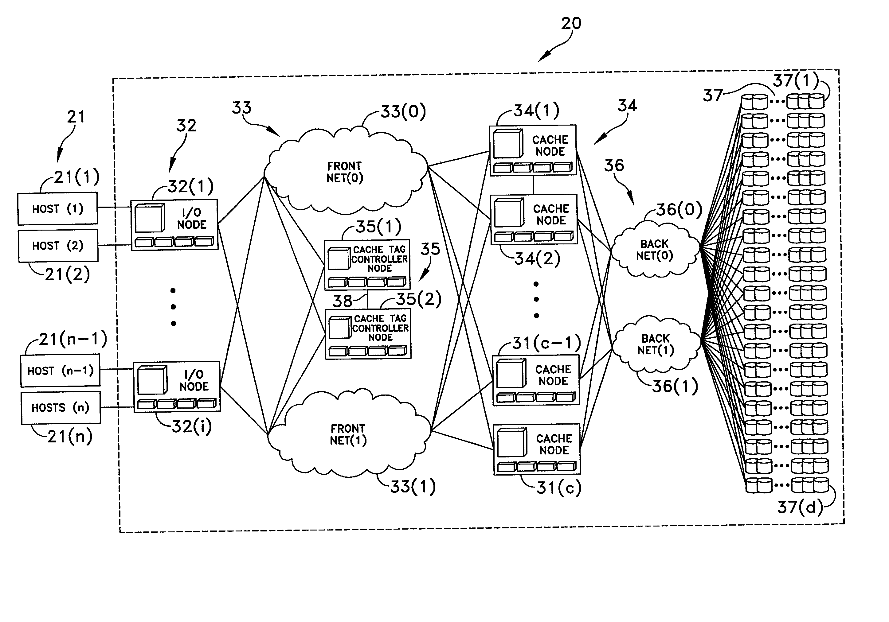
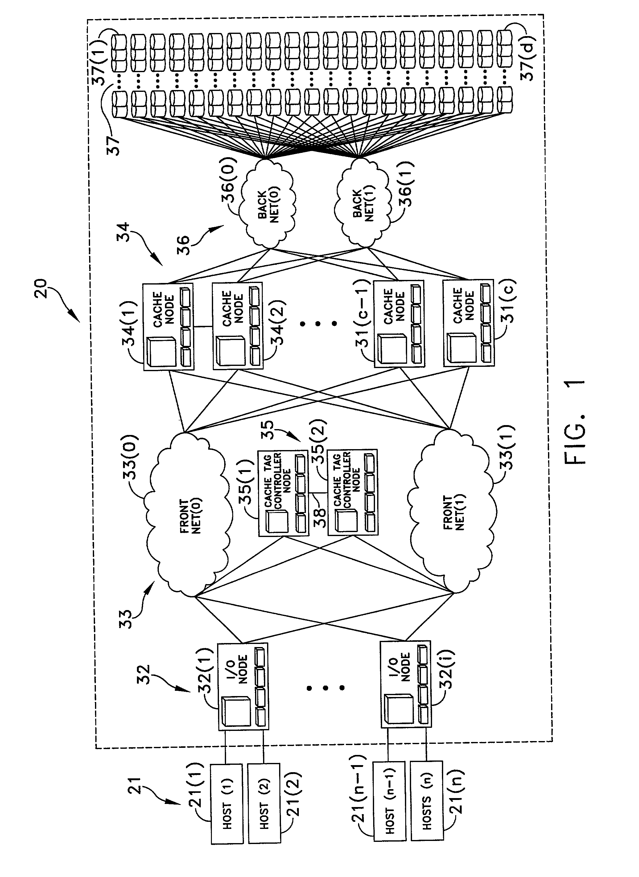
[0032] FIG. 1 depicts a distributed cache, scalable data storage facility 20 that embodies this invention. This data storage facility 20 connects for operation for one or more data processors or hosts 21. In this particular embodiment, FIG. 1 depicts four hosts shown as HOST(1) 21(1), HOST(2) 21(2), HOST(n-1) 21(n-1) and HOST(n) 21(n). Each host system has the capability of issuing data transfer requests in a known syntax. In the following discussion, such requests are called host requests. Generally such host requests include an operation code and an address, usually to a virtual location. For example, a host request address may identify a data storage location in physical disk drives or other storage media by identifying a logical volume, an initial address in that logical volume and, for requests that define blocks of different sizes, a block size parameter. The operation code defines a specific operation. Two such operations are important to an understanding of this invention. T...


PUM


Abstract

The data storage facility includes a plurality of data storage devices coupled through multi-path connections to cache memory. A plurality of interfaces to host processors communicates with the cache memory and with cache tag controllers that define the cache memory again over multiple paths.

Description

[0001] 1. Field of the Invention[0002] This invention generally relates to data processing systems and more specifically to data storage facilities for use in such data processing systems.[0003] Description of Related Art[0004] Early data processing systems comprised a single processor, random access memory and a data storage facility in the form of a single magnetic disk drive. Such systems are still in wide use by small businesses and individuals and as terminals or nodes in a network. The capacities of the single magnetic disk drive associated with such systems are now into the hundred-gigabyte (i.e., 100*10.sup.9 bytes) range. However, there are many applications in which even these increased capacities no longer are sufficient.[0005] Increased storage capacities required by multi-processing systems with multiple access and increased database sizes have been realized by the development of data storage facilities with disk array storage devices. Concurrently with this development...

Claims


Application Information

Patent Timeline
IPC IPC(8): G06F3/06G06F12/08
CPCG06F3/0601G06F2003/0697G06F12/0866G06F12/0815G06F3/0689G06F3/0676G06F3/0638G06F3/0646G06F3/0613G06F3/0614
Inventor CHALMER, STEVEN R.MCCLURE, STEVEN T.NIVER, BRETT D.WHEELER, RICHARD G.
Owner EMC IP HLDG CO LLC
Why Eureka
Try Eureka