
Radio communication system, radio communication apparatus and radio communication method, and computer program

Active Publication Date: 2003-08-28
SONY CORP
View PDF7 Cites 38 Cited by
  • Summary
  • Abstract
  • Description
  • Claims
  • Application Information

AI Technical Summary

Benefits of technology

[0024] There is another demand for a radio communication system, a radio communication apparatus and a radio communication method and a computer program which are advantageous and in which a mobile station may suitably perform communication according to a TDMA frame synchronized by a control channel which is transmitted from a base station for each cell.
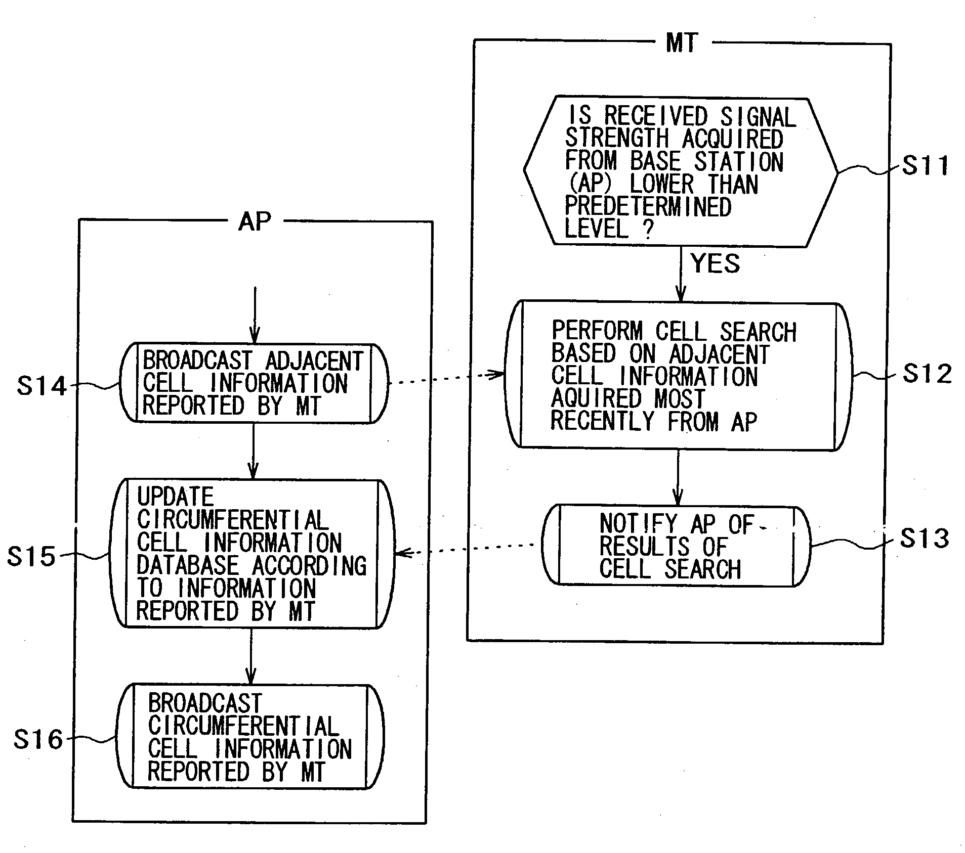
[0050] In the radio communication system according to the present invention, management of adjacent cell information acquired by mobile stations is centralized in a base station. The base station may provide the mobile station with the information of an adjacent cell when the mobile station performs an adjacent cell search. The adjacent cell information may include a TDMA frame offset between cells and the like. Thus the mobile station may receive a broadcast channel of the adjacent cell at an appropriate timing based on the adjacent cell information. As a result, the mobile station does not need to perform an unnecessary reception operation in the event of handoff, thus constituting an effective measure for reducing the power consumption of the mobile station.

Problems solved by technology

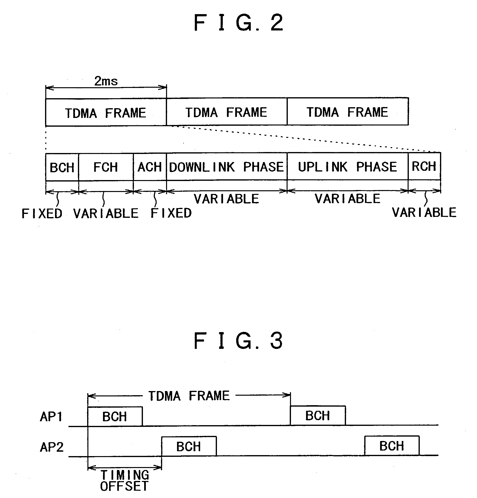
However, in a small radio communication system such as a wireless LAN, it is often the case that neither connection nor synchronization between the base stations is established, a transmission timing of the control channel such as the beacon is different for each base station, and the TDMA frames are not synchronized.
Maintaining the reception process for 2 milliseconds constitutes a disadvantage from the viewpoint of power consumption.

Method used


Image

  • Radio communication system, radio communication apparatus and radio communication method, and computer program
  • Radio communication system, radio communication apparatus and radio communication method, and computer program
  • Radio communication system, radio communication apparatus and radio communication method, and computer program

Examples


Embodiment Construction

[0064] Preferred embodiments of the present invention will be described in detail below, with reference to the attached drawings.

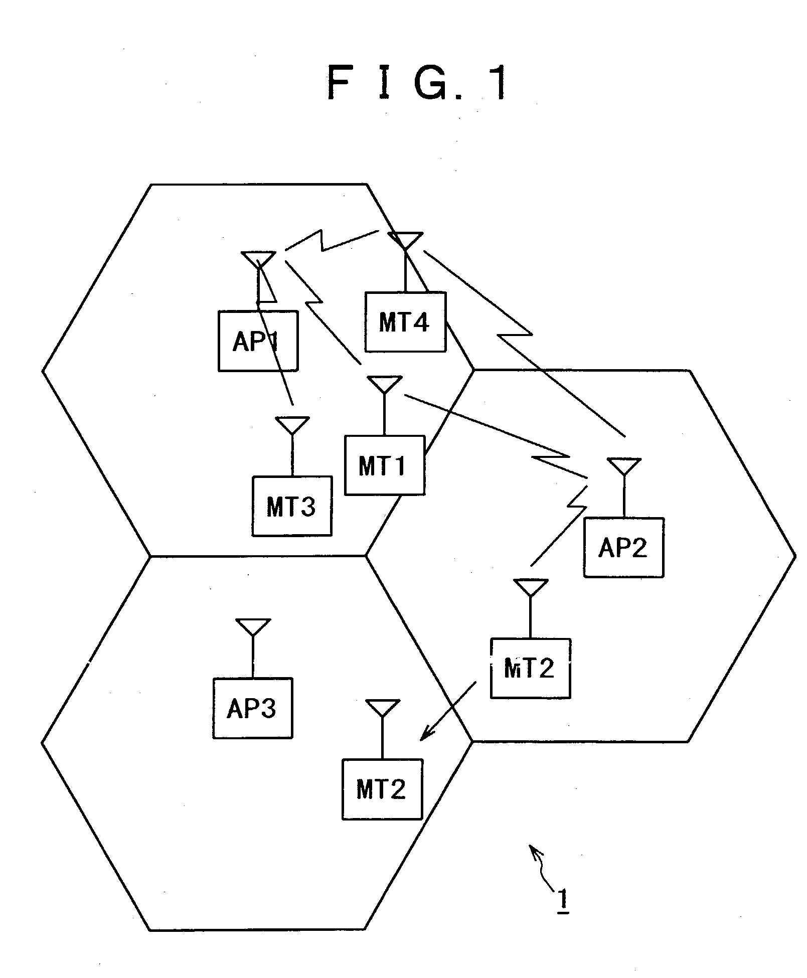
[0065] In FIG. 1, there is schematically shown a general construction of a radio communication system 1 according to a preferred embodiment of the present invention.

[0066] A radio communication system 1 is a multi-cell construction in which base stations (not shown) are disposed at predetermined intervals. In the example as shown in the figure, base stations AP1, AP2 and AP3 constitute radio communication cells, respectively. A plurality of mobile stations may be simultaneously accommodated within each cell by means of time division multiple access (TDMA). Four mobile stations MT1-MT4 perform radio communications, freely moving between the cells. However, we assume in the preferred embodiment of the present invention that the radio communication system 1 is a radio communication network of small size such as a wireless LAN and does not establish connection...


PUM


Abstract

Under a multi-cell radio communication environment where connection between cells or TDMA frame synchronization is not established, a mobile station carries out an adjacent cell search under low power consumption. Adjacent cell information acquired through search by the mobile station is managed centered on a base station and may be provided by the base station as adjacent cell information, when the mobile station carries out the adjacent cell search. The adjacent cell information includes, for example, a TDMA frame offset between cells so that the mobile station receives a broadcast channel of the adjacent cell at appropriate timing based on the adjacent cell information and therefore does not need to perform unnecessary reception operation in the event of a handoff.

Description

[0001] This application claims priority to Japanese Patent Application No. JP 2002-053295, filed on Feb. 28, 2002, the disclosure of such application being herein incorporated by reference to the extent permitted by law.[0002] 1. Field of the Present Invention[0003] The present invention relates to a radio communication system, a radio communication apparatus and a radio communication method, and a computer program in which a plurality of mobile stations simultaneously communicate with a base station by means of multiple accesses, in particular to a radio communication system, a radio communication apparatus and a radio communication method, and a computer program in which time division multiple access (TDMA) communication is carried out for each base station cell.[0004] More particularly, the present invention relates to a radio communication system, a radio communication apparatus and a radio communication method and a computer program in which a mobile station performs communicat...

Claims


Application Information

Patent Timeline
IPC IPC(8): H04J3/00H04W48/12
CPCH04W48/12Y02D30/70
Inventor NISHIYAMA, FUMIHIROKUNIHIRO, TAKUSHIYAMAURA, TOMOYASAKODA, KAZUYUKI
Owner SONY CORP
Learn More