
Common mode choke coil and method of manufacturing the same

a choke coil and common mode technology, applied in the field of common mode choke coils, can solve the problems of large impedance to the normal mode noise at a high-frequency band, abnormal signal wave form,

Inactive Publication Date: 2003-09-04
TAIYO YUDEN KK
View PDF10 Cites 11 Cited by
  • Summary
  • Abstract
  • Description
  • Claims
  • Application Information

AI Technical Summary

Problems solved by technology

Therefore, the powder of the magnetic material will inevitably have to be interposed between the two metallic coils.
As a consequence, if the common mode choke coil is connected to a signal line, the impedance works as a load to the signal, resulting in an abnormality in the signal wave form.
However, this arrangement is not preferable as a common mode choke coil because the frequency characteristics become high in Q value if the conducting wires are not covered on their outside with a sintered magnetic material.
In this case, if the distance between the metallic conducting wires is wide apart, capacitance or stray occurs between the metallic conducting wires, with the result that the impedance to the normal mode noises at a high-frequency band becomes large.

Method used


Image

  • Common mode choke coil and method of manufacturing the same
  • Common mode choke coil and method of manufacturing the same
  • Common mode choke coil and method of manufacturing the same

Examples


Embodiment Construction

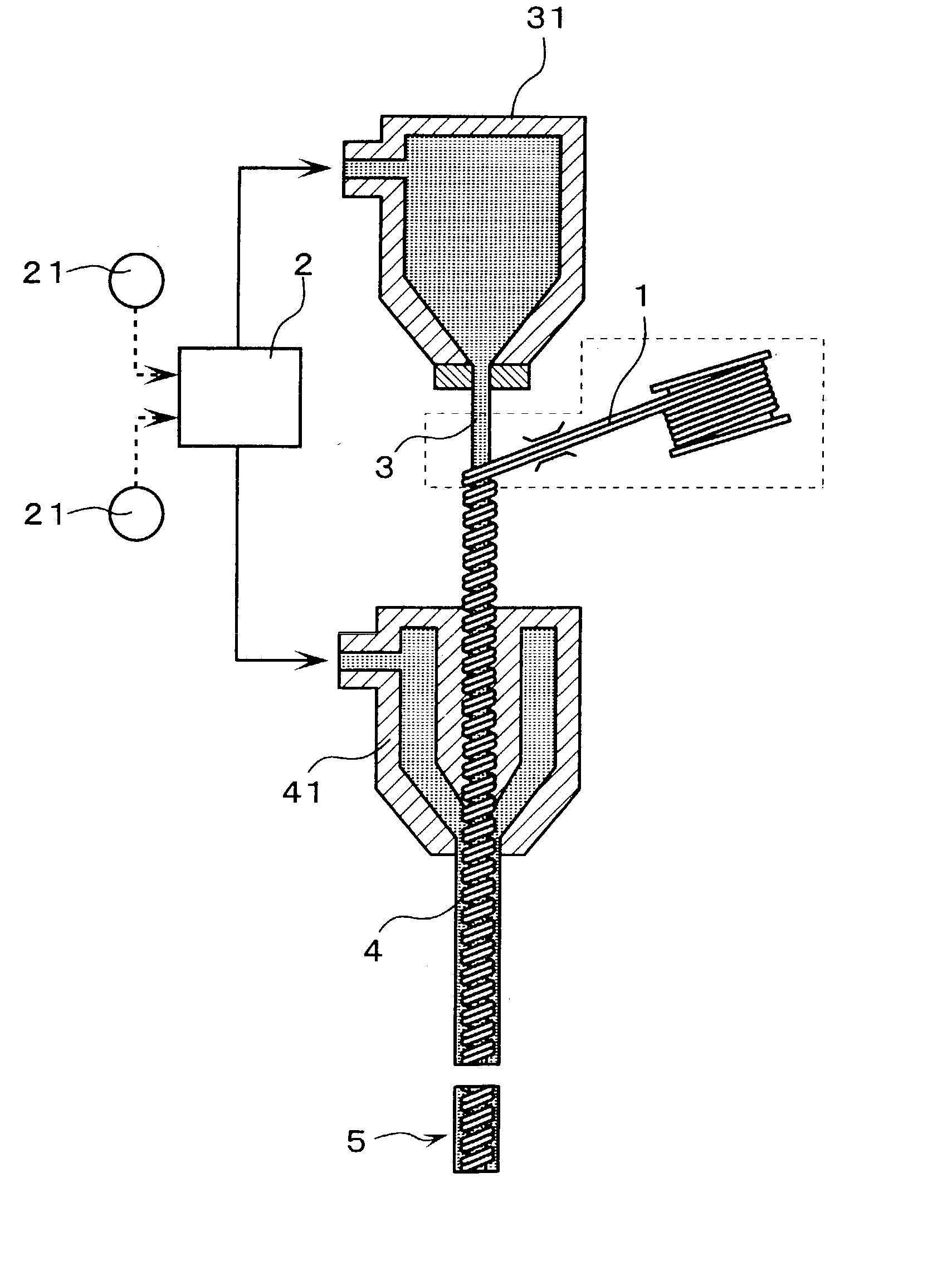
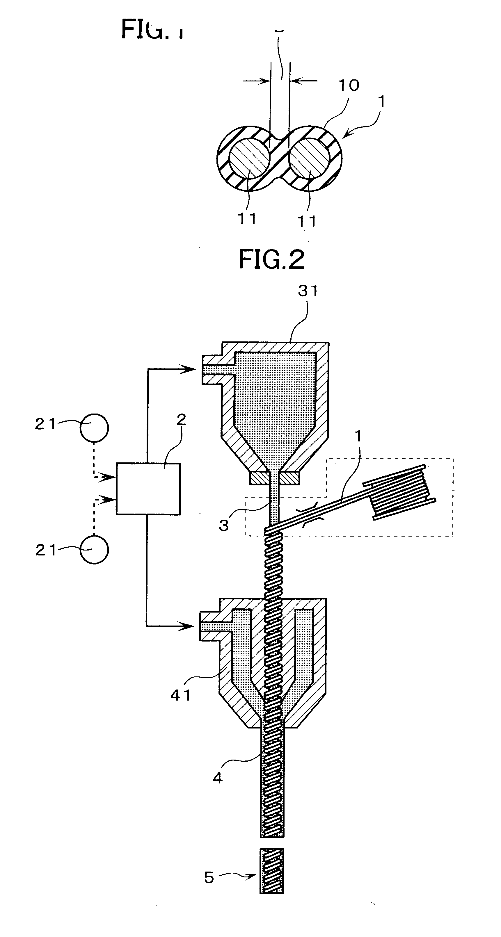
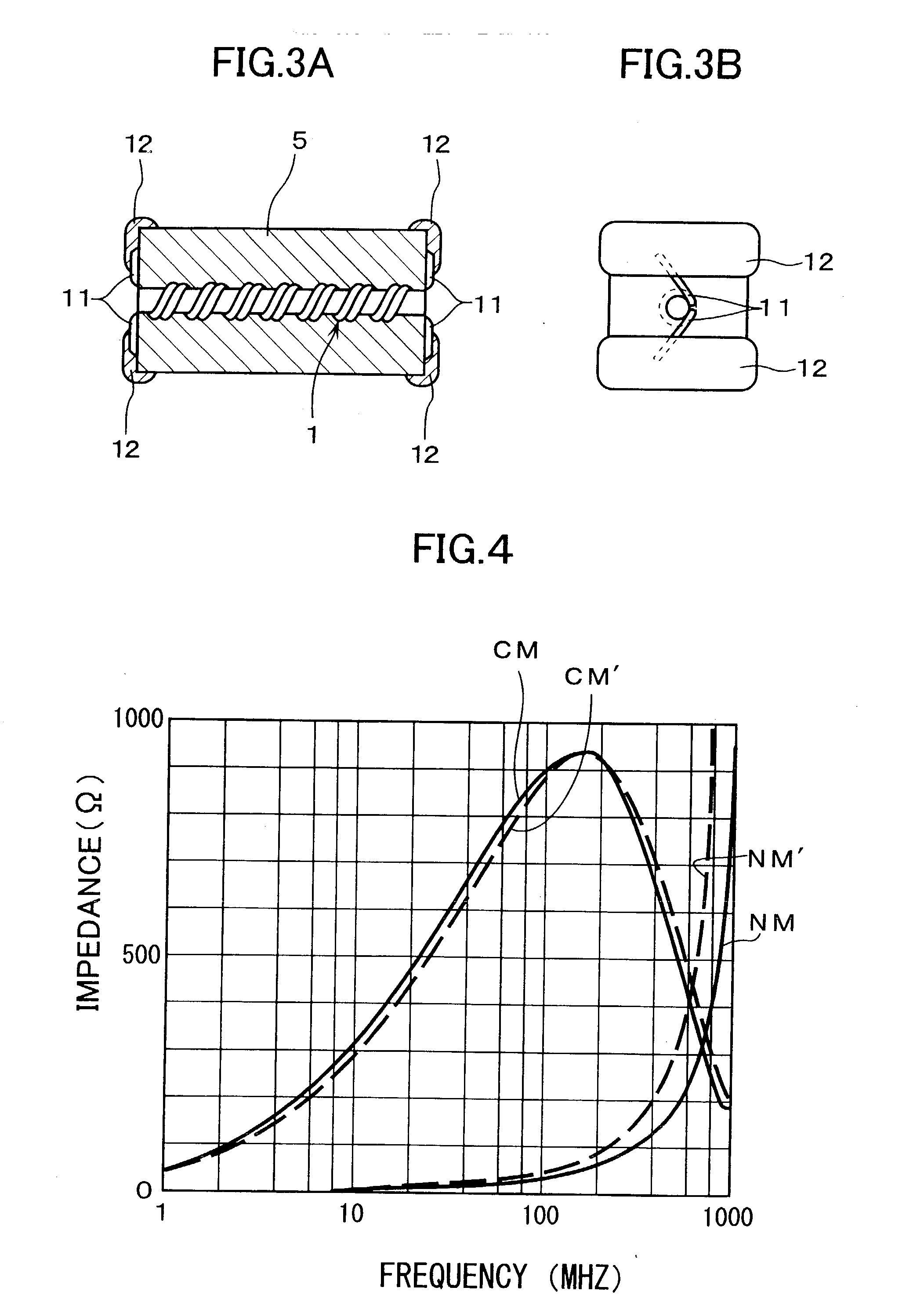
[0021] With reference to FIG. 1, reference numeral 1 denotes coated conducting wires which are manufactured by integrally coating two metallic conducting wires 11 with a non-magnetic and electrically insulating material 10. The metallic conducting wires 11 are made of a suitable material such as silver, palladium, gold, or the like. The coated conducting wires 1 may also be manufactured by coating each of the metallic conducting wires 11 with a non-magnetic and electrically insulating material 10 and thereafter by integrating or combining the coated conducting wires together by melting and adhering the electrically insulating material 10. As the non-magnetic and electrically insulating material, a material which does not diminish or disappear at the sintering temperature, such as heat-resistant glass, ceramic, or the like, is preferable. The distance D between both the metallic conducting wires 11 can be adjusted to a desired one by adjusting the coating thickness at the time of coa...


PUM

PropertyMeasurementUnit
Electrical conductoraaaaaaaaaa

Abstract

A common mode choke coil has a plurality of metallic conducting wires buried into a sintered magnetic material such that the metallic conducting wires are proximate to each other and an electrode mounted on a surface of the sintered magnetic material so as to be connected to each end portion of each of the metallic conducting wires. The metallic conducting wires are integrally coated with a non-magnetic and electrically insulating material at a predetermined distance between each of the metallic conducting wires to thereby form coated conducting wires. The coated conducting wires buried into the sintered magnetic material are thus obtained.

Description

[0001] 1. Field of the Invention[0002] The present invention relates to a common mode choke coil for removing common mode noises which are superimposed in a power supply line, a signal line or the like of an electronic equipment. The present invention also relates to a method of manufacturing the common mode choke coil.[0003] 2. Description of the Related Art[0004] The following common mode choke coil and a method of manufacturing the same are known from Japanese Published Unexamined Patent Application No. 304035 / 1993. Namely, inside a resin which is mixed with powder of a magnetic material, two metallic coils which have the same number of winding and the same winding direction are buried substantially in parallel to each other in a substantially coaxial manner, whereby a formed body made of a resin mixed with powder of magnetic material is obtained. An electrode which is electrically connected to a corresponding end portion of each of the metallic coils is thereafter formed.[0005] ...

Claims


Application Information

Patent Timeline
IPC IPC(8): H01F17/00H01F17/06H01F27/32H01F41/12H01F37/00H01F41/02
CPCH01F27/323H01F37/00H01F41/0246Y10T29/49073Y10T29/49071Y10T29/4902Y10T29/49076H01F17/06
Inventor TAKAYAMA, MANABUTAKETOMI, KOUJIKUMAHORA, TETSUO
Owner TAIYO YUDEN KK
Learn More