Circuit for applying suplementary voltages to RF multipole devices

a multi-pole device and circuit technology, applied in the direction of particle separator tube details, separation processes, instruments, etc., can solve the problems of affecting the injection, complicating the design of such a device, and requiring a much larger and substantially more expensive ac transformer design, so as to achieve the effect of minimizing the axis potential

Inactive Publication Date: 2003-09-18
THERMO FINNIGAN
View PDF0 Cites 38 Cited by
  • Summary
  • Abstract
  • Description
  • Claims
  • Application Information

AI Technical Summary

Benefits of technology

0009] A two-dimensional RF quadrupole field is established in the x and y direction by applying a sinusoidal RF voltage, 2V.sub.RFCos(.omega.t), between the X and Y rod electrode pairs. For most practical devices, the range for angular frequency, .omega., of the applied voltage typically corresponds to frequencies of between 0.5 to 2.5 MHz. The amplitude of this main trapping field voltage, V.sub.RF, may typically range to exceed 4 KV peak voltage during ion isolation and scanning steps of mass spectrometric experiments. While it is feasible to accomplish this by applying a RF voltage 2V.sub.RFCos(.omega.t) to only one pair of rod electrodes while maintaining the other pair at RF "ground", this imposes a RF potential at the axis of the device (bias potential) of V.sub.RFCos(.omega.t). While this has no effect on ion motion once the ions are within the device, this RF axis potential leads to strong z axis RF potential gradients at the entrance to the device which interfere with the injection of ions from an external source. Symmetric application of voltages V.sub.RFCos(.omega.t) and -V.sub.RFCos(.omega.t) to the X and Y rod pairs respectively minimizes the axis potential. However this means that to create the desired superposition of RF, DC and AC fields within the device, corresponding RF, DC and AC voltages must be simultaneously applied to at least some of the electrodes.
0010] In order to enable the superposition of a weak axial DC trapping potential upon the main two-dimensional quadrupole field, each of the four rod electrodes may be divided into segments so as to allow separate DC bias voltages, V.sub.DC.sub..sub.--.sub.FRONT, V.sub.DC.sub..sub.--.su-b.CENTER, V.sub.DC.sub..sub.--.sub.BACK, to be applied to the rod segments comprising the Front, Center and Back sections of the structure. These DC rod bias or

Problems solved by technology

While this has no effect on ion motion once the ions are within the device, this RF axis potential leads to strong z axis RF potential gradients at the entrance to the device which interfere with the injection of ions from an external source.
Although this approach has been successfully used, in many cases a major disadvantage of this approach is that th

Method used


Image

  • Circuit for applying suplementary voltages to RF multipole devices
  • Circuit for applying suplementary voltages to RF multipole devices
  • Circuit for applying suplementary voltages to RF multipole devices

Examples


Embodiment Construction

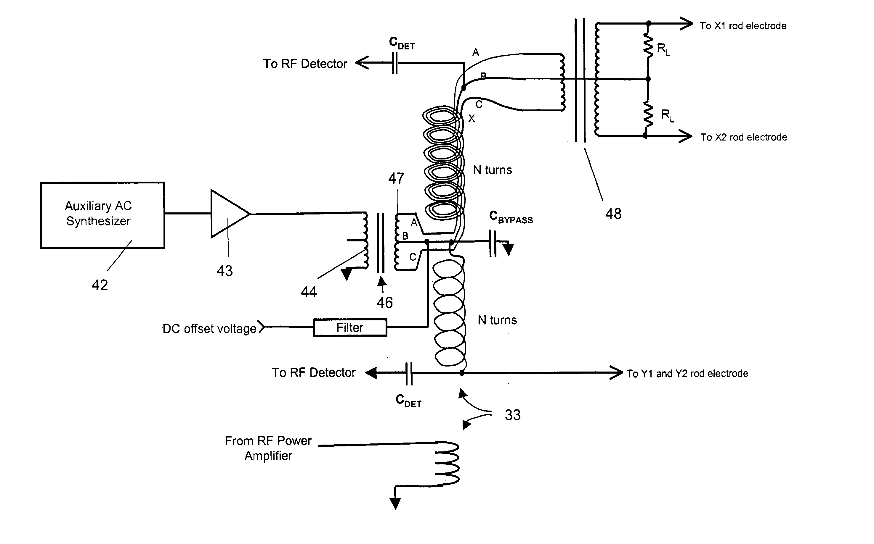
[0033] A brief discussion of the design and construction of RF tuned transformers 23 is helpful in the understanding of the present invention. The reason that such devices are used is that it is possible to generate high RF voltages in the frequency range needed for RF quadrupole / multipole devices with relatively modest amounts of RF power. The secondary winding of the transformer is, in essence, a very large air cored solenoidal inductor. The connection of the secondary winding to the rod electrodes puts an almost purely capacitive reactance across this inductor creating an LC resonant circuit. Since there is essentially no resistive component to this load the only source of damping is the resistance of the wire in the coil windings and resistive losses associated with induced currents in the circuit enclosure. Hence this LC circuit has a very high quality factor, Q, and a correspondingly narrow resonant bandwidth. A basic characteristic of such circuits is that if you drive them w...


PUM


Abstract

A circuit is described for applying RF and AC voltages to the elements or electrodes of an ion trap or ion guide. The circuit includes an RF transformer having a primary winding and a secondary winding. The secondary winding includes at least two filars. A broadband transformer adapted to be connected to a source of AC voltage applies AC voltage across the low-voltage end of two of the filars. Another broadband transformer connected to the filars at the high-voltage end provides a combined RF and AC output for application to selected electrodes. Also described is a circuit employing a multi-filar RF transformer and broadband transformers for applying RF and AC voltages to spaced rods of a linear ion trap. Also described is a circuit employing a multi-filar RF transformer and broadband transformers for applying RF and AC voltages to the electrodes in each section of a linear ion trap of the type having a center section and end sections, and different DC voltages to the electrodes in the end sections.

Description

[0001] This application claims priority to provisional Application Serial No. 60 / 354,389 filed Feb. 4, 2002 and Serial No. 60 / 355,436 filed Feb. 5, 2002.BRIEF DESCRIPTIONS OF THE INVENTION[0002] This invention relates generally to RF (radio frequency) quadrupole and inhomogeneous field devices such as three-dimensional RF quadrupole ion traps and two-dimensional RF quadrupole mass filters or ion traps, and more particularly to a circuit which allows application of supplementary AC voltages to electrodes of RF quadrupole field devices when the voltages used to generate the main RF quadrupole field are simultaneously being applied to the same electrodes.[0003] There is a wide variety of RF quadrupole and multipole field devices used for mass spectrometry and related applications. These devices are used for containment, guiding, transport, ion fragmentation, mass (mass-to-charge ratio) selective sorting, and production of mass (mass-to-charge ratio) spectra of beams or populations of i...

Claims


Application Information

Patent Timeline
IPC IPC(8): G21K1/08H01J3/14H01J3/26H01J49/00H01J49/02H01J49/38H01J49/42
CPCH01J49/022H01J49/423H01J49/422
Inventor SYKA, JOHN E.P.
Owner THERMO FINNIGAN
Why Eureka
Try Eureka