

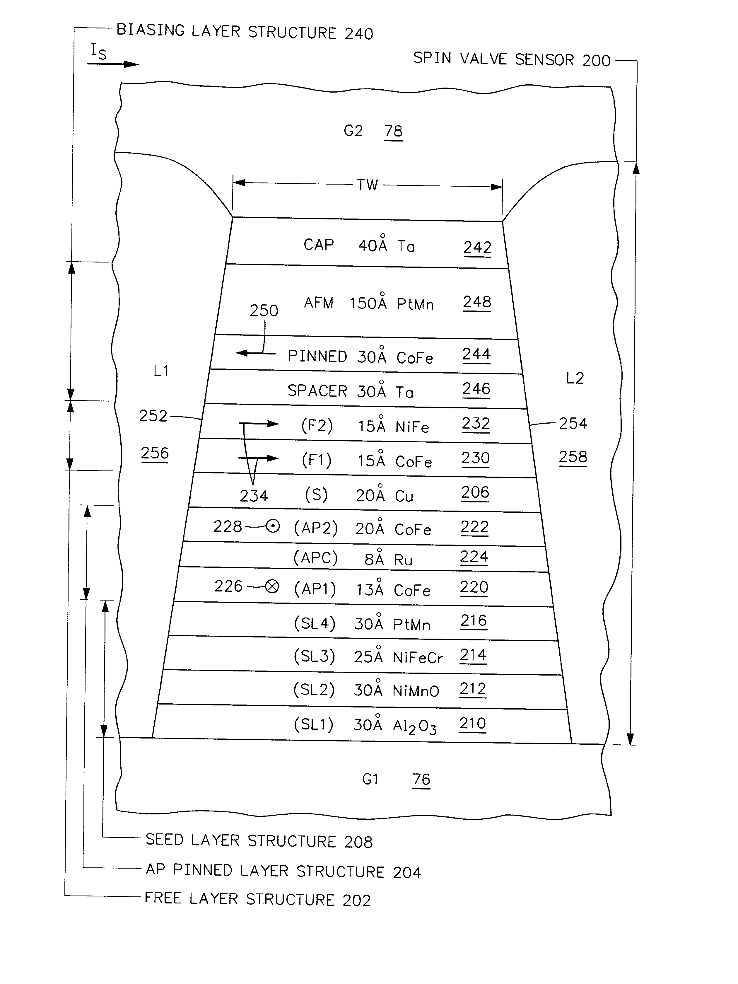
Spin valve sensor with in-stack biased free layer and antiparallel (AP) pinned layer pinned without a pinning layer
a technology of in-stack biasing and free layer, which is applied in the direction of data recording, magnetic recording head, instruments, etc., can solve the problems of unfavorable extraneous field, corrosive materials, and uneven magnetic field through the free layer between the first and second side surfaces
- Summary
- Abstract
- Description
- Claims
- Application Information
AI Technical Summary
Benefits of technology
Problems solved by technology
Method used
Image

Examples
Embodiment Construction
were tested at the coupon level and Examples 1 and 2 were further tested at the row level. At the coupon level a single sensor is fabricated on a glass substrate and is not lapped to the ABS. Since lapping causes the aforementioned ABS compressive stress the ABS compressive stress due to lapping is not present at the coupon level. The row level is a row of read heads including their read sensors and is taken from a slider substrate where rows and columns of such read heads have been fabricated. After dicing the row of read heads from the slider substrate, the row is lapped to the ABS which causes the aforementioned compressive stress.
[0052] At the coupon level the magnetoresistive coefficient dr / R, the intrinsic uniaxial anisotropy field H.sub.Ki, the magnetostriction .lambda. (AP) of the AP pinned layers, the magnetostriction uniaxial anisotropy field H.sub.K.lambda., the resistance of the sensor R.sub.S and the magnetostriction of the free layer .lambda. (FL) were determined and / o...
PUM
 Abstract
Description
Claims
Application Information