Sensor and method for range measurements using a TDI device

Inactive Publication Date: 2003-10-02
INSTITUT NATIONAL D'OPTIQUE
View PDF0 Cites 11 Cited by
  • Summary
  • Abstract
  • Description
  • Claims
  • Application Information

AI Technical Summary

Benefits of technology

[0033] Advantageously, the use of a TDI device in the place of matrix type photodetector arrays as detection means for 3-D triangulation based sensors allows certain performance gains. The main performance gain is in the number of 3D points per profile combined with a high profile rate that can be achieved using these detectors. Using relatively inexpensive and standard commercially available TDI devices in accordance with the present invention, it is possible to obtain a 3-D profile of 2048 points at a rate of 864 Hz. and using the partial scanning technique described below, 2048 points at a rate of 1728 Hz can be achieved.

Problems solved by technology

One drawback of existing cameras available for range and 3-D measurements is that manufacturers usually provide such cameras in a limited amount of shapes and sizes.
If high lateral resolution, that is points per profile, is desired (ex: 2048 points per profile), very expensive and slow (maximum frame rate of 30 Hz) 2048.times.2048 arrays need to be used.
While TDI cameras are frequently used for imaging in web type industrial inspection applications, to date, they have not been used as the detection means for range sensors.
While it seems that a TDI line array can readily replace traditional line array detectors commonly used as detection means for single point type laser and flying spot laser scanning 3-D sensors, this in fact has not been the case.
One reason is that the performance gain, in terms of speed or resolution of these types of 3-D sensors, would not be increased by the use of a TDI sensor and with the added difficulty of synchronizing the motion of the object with the sensor, manufacturers have not adopted this approach.

Method used


Image

  • Sensor and method for range measurements using a TDI device
  • Sensor and method for range measurements using a TDI device
  • Sensor and method for range measurements using a TDI device

Examples


Embodiment Construction

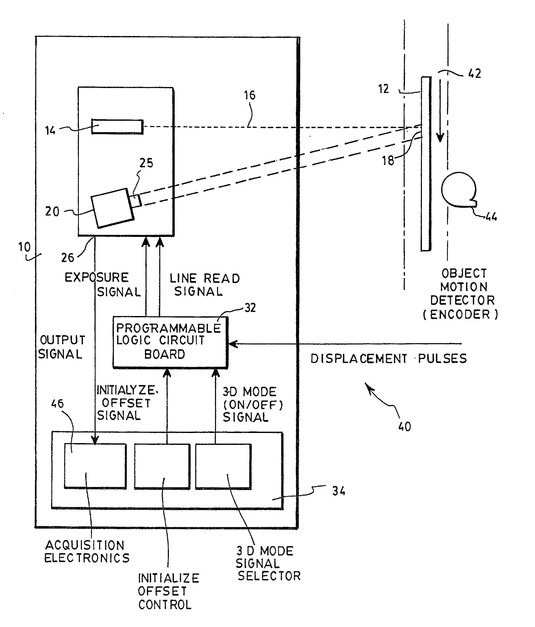
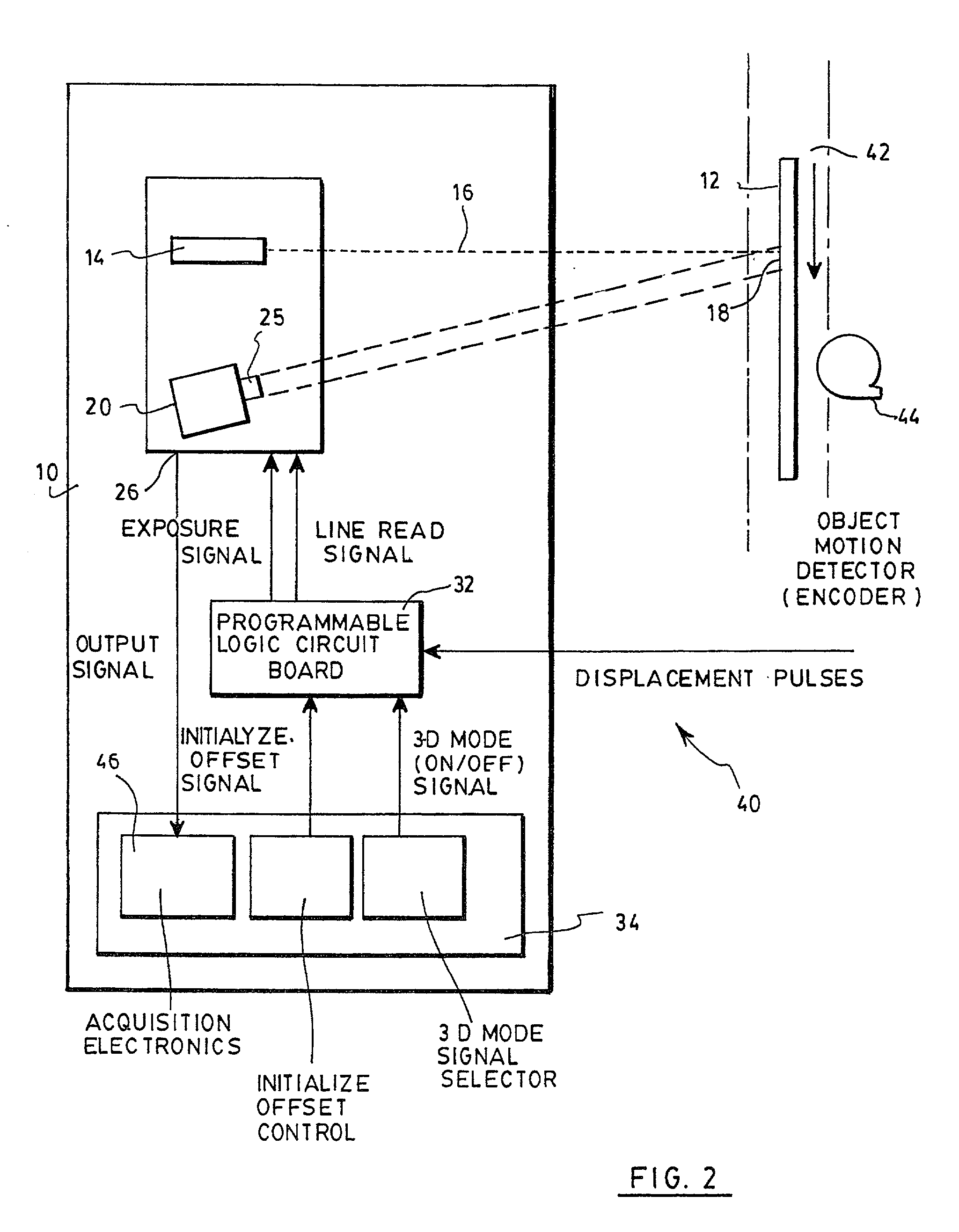
[0039] With reference to FIG. 2, there is shown a preferred embodiment of a sensor 10 for measuring the range to a target object 12.

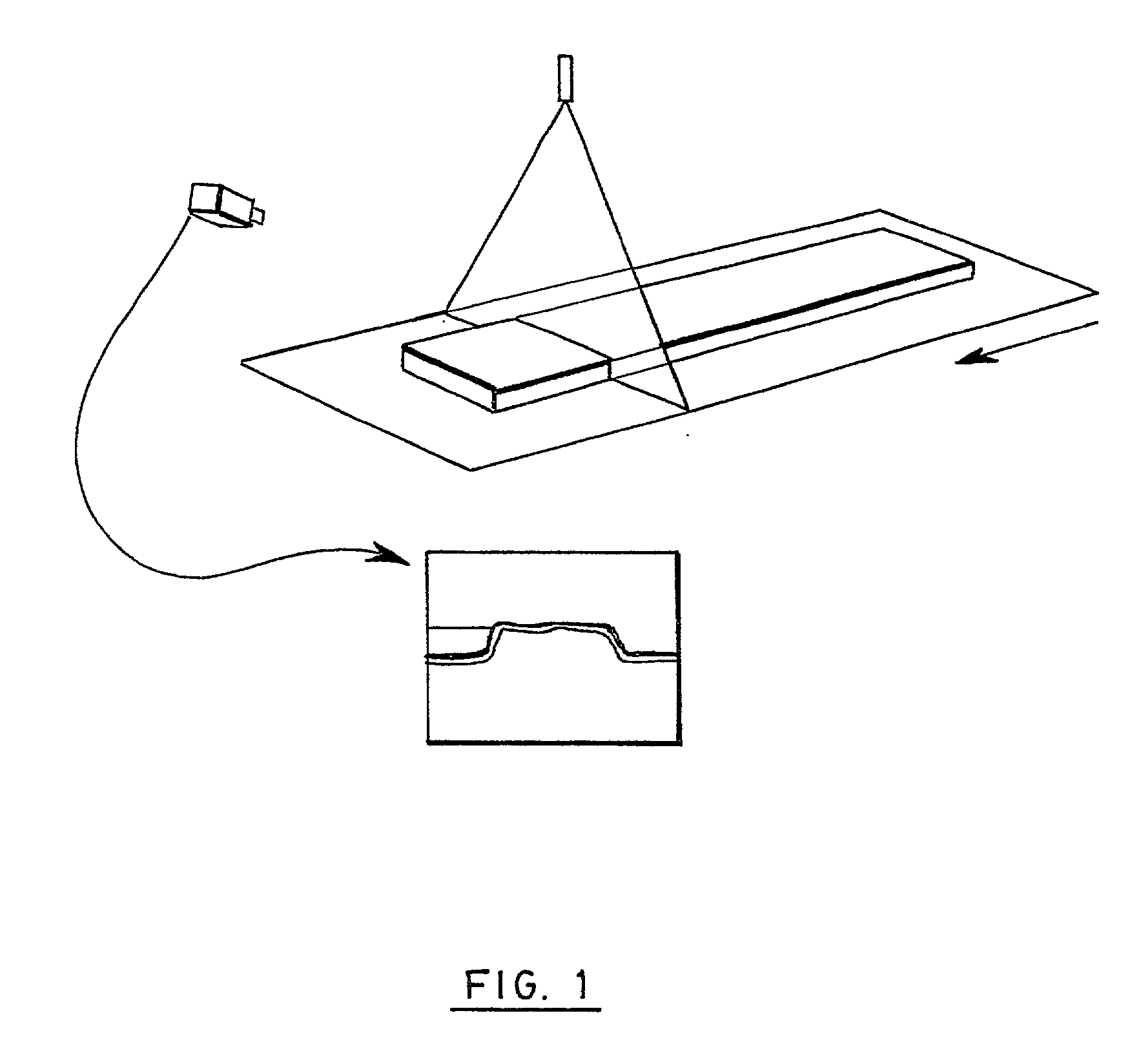
[0040] The sensor first includes a light source 14 generating a light beam 16. In the preferred embodiment, the light source 14 is a uniform intensity laser line projector, the light beam 16 therefore being line-shaped. For the purposes of the invention, the light beam should be structured, that is that it should define a pattern. The light beam 16 is projected towards an exposition area 18 on the target object 12, and reflected by this object. The shape of the reflected light beam will help determine the range of the surface of the object 16 along the pattern defined by the light beam 16.

[0041] A TDI device 20 is provided and positioned to detect the reflection of the light beam 16 on the target object 12 within the exposition area 18. A camera lens 25 is preferably provided to image the reflection of the light beam 16 on the appropriate optical compon...


PUM


Abstract

A sensor and method for taking range measurements of a target object using a TDI device as a detector are provided. The device is positioned to detect reflections of a structured light beam on the target object. To avoid losing the range information in the TDI process, the exposition of the device to the reflection of the light beam is restricted to the first integration period of the acquisition cycle of the TDI device, so that the output of the device provides line by line an image of the light beam on the target object during this first integration period.

Description

[0001] The present invention relates to 3-D sensing and more particularly concerns a sensor and a method for making range measurements using a TDI array.[0002] In the field of information sensing, machine vision technologies provide valuable information about the environment and about specific objects of interest through close inspection. Many known 3-D data acquisition systems exist that use 3-D sensors based on the triangulation principle. In such systems, a specific known and often fixed pattern of illumination, i.e. structured illumination, is projected from a laser onto an object to be measured. A digital camera, generally based on a charge coupled device (CCD) matrix array, is placed at a known fixed and oblique angle with respect to the light projector. The intersection between the emitted light pattern and the field of view of the digital camera defines the operating range of the 3-D sensor. The position of the illuminated points on the object surface that are imaged on the ...

Claims


Application Information

Patent Timeline
IPC IPC(8): G01S7/487G01S17/46G01S17/89
CPCG01S7/487G01S17/89G01S17/48
Inventor LAURENT, JOHNBOULANGER, DENIS
Owner INSTITUT NATIONAL D'OPTIQUE
Why Eureka
Try Eureka