Pipettor and externally sealed pipette tip

a technology of pipette tip and pipette, which is applied in the field of pipette tip, can solve the problems of high maintenance cost of such o-rings, use of o-rings, and increased manufacturing costs, and achieve the effect of being cheap to manufactur

Inactive Publication Date: 2003-10-09
YIU FELIX H
View PDF1 Cites 25 Cited by
  • Summary
  • Abstract
  • Description
  • Claims
  • Application Information

AI Technical Summary

Benefits of technology

0025] It is yet another object of the present invention to provide a pipette tip that is inexpensive to manufacture.
0026] It is yet another object of the present invention to provide a pipette tip that is usefully implemented in both manual and automated processes.

Problems solved by technology

Unfortunately, in practice, such multiple pipette tip mounting procedures often result in some of the pipette tips being mounted at different axial orientations on some of the mounting shafts or mandrels.
Several disadvantages arise from the use of O-rings, not the least of which is the greater expense and manufacturing.
Additionally, O-rings require lubrication and other activities leading to high maintenance with respect to such O-rings.
O-rings need replacement from time to time and due to compression introduce an element of unreliability into the volumes pipetted especially as needed amounts of pipetted liquids become smaller and smaller and progress further and further into the microvolume range.

Method used


Image

  • Pipettor and externally sealed pipette tip
  • Pipettor and externally sealed pipette tip
  • Pipettor and externally sealed pipette tip

Examples


Embodiment Construction

)

[0045] The detailed description set forth below in connection with the appended drawings is intended as a description of presently-preferred embodiments of the invention and is not intended to represent the only forms in which the present invention may be constructed and / or utilized. The description sets forth the functions and the sequence of steps for constructing and operating the invention in connection with the illustrated embodiments. However, it is to be understood that the same or equivalent functions and sequences may be accomplished by different embodiments that are also intended to be encompassed within the spirit and scope of the invention.

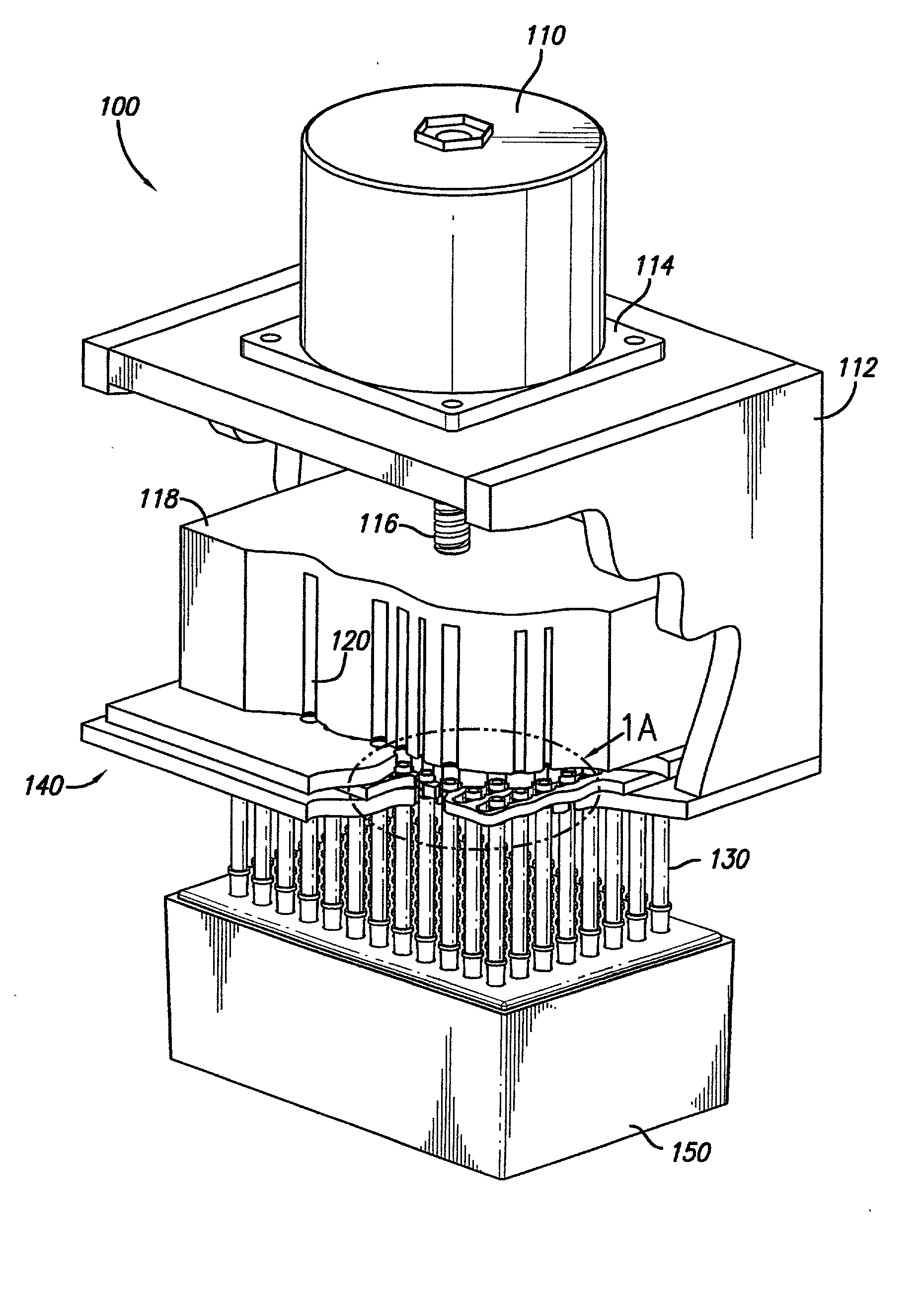
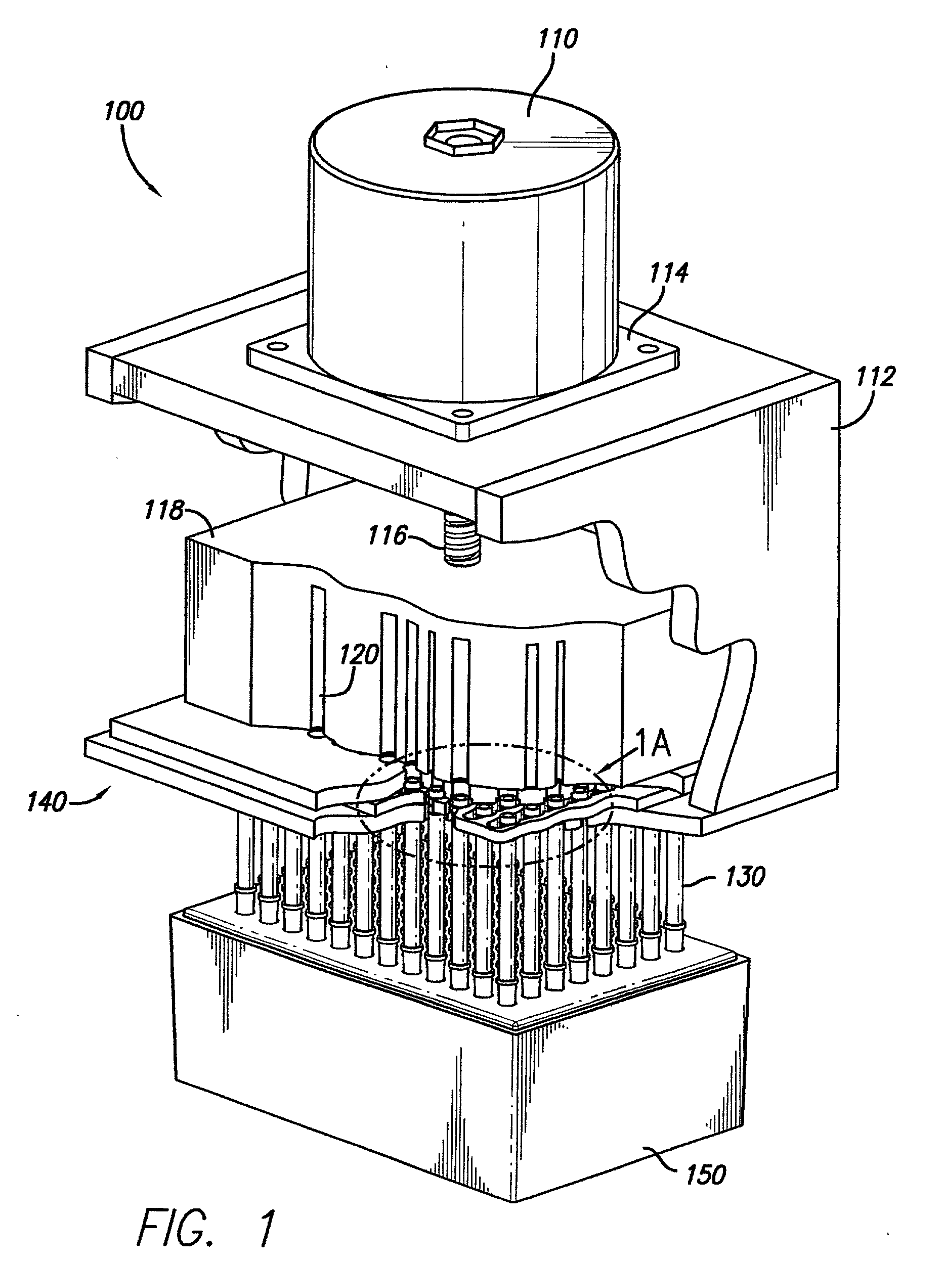
[0046] The automatic and motorized pipettor 100 is shown in FIG. 1 in a perspective and partial cutaway view indicating a variety of the different features of the present invention. A precision motor 110 (that may operate in a stepwise manner) is attached to the chassis 112 by a motor mount 114. The motor 110 may be controlled by a co...


PUM

PropertyMeasurementUnit
angleaaaaaaaaaa
forcesaaaaaaaaaa
torquesaaaaaaaaaa

Abstract

A pipettor uses no pistons in order to provide highly automated, precise and accurate pipetting operations. Additionally, a self-aligning pipette tip enables better engagement of such pipette tips by the pipettor. The pipette tips may be automatically engaged and locked into place by the pipettor and may be automatically disengaged to enable highly-automated pipetting processes for industrial and laboratory purposes. Open proximal ends of the pipette tips are engaged by a pipette block, which then forms a temporary seal with the individual pipette tips. Displacement of the pipette block with respect to the pipette tips increased or decreases the effective volume of the pipette tip allowing it to aspirate or expel fluids in a precise, accurate, and predictable way.

Description

[0001] 1. Field of the Invention[0002] This invention relates to pipettors and pipette tips and more particularly to a piston free pipettor and a self-aligning and self-sealing pipette tip.[0003] 2. Description of the Related Art[0004] Pipetting systems are used in laboratories for the transfer of relatively small quantities of liquids in a precise and accurate manner. The liquid is normally drawn into the tips by suction and is subsequently released into the wells of microtiter plates or other receptacles. Frequently the transfer involves samples, which are moved from one set of spaced receptacles to another set of receptacles.[0005] The use of pipette devices for the transfer and dispensing of precise quantities of fluids in analytical systems is well known as is the use of disposable tip members for such pipettes. Disposable tips accommodate the serial use of such pipette devices in the transfer of different fluids without carryover or contamination of a second sample from a disp...

Claims


Application Information

Patent Timeline
Patent Type & Authority Applications(United States)
IPC IPC(8): B01L3/02G01N35/10
CPCB01L3/0227B01L3/0279G01N35/1074B01L2200/0689B01L2300/0838B01L2200/025
Inventor YIU, FELIX H.
Owner YIU FELIX H
Why Eureka
Try Eureka