Eureka AIR delivers breakthrough ideas for toughest innovation challenges, trusted by R&D personnel around the world.

Multispectral or hyperspectral imaging system and method for tactical reconnaissance

a multi-spectral or hyperspectral imaging and tactical reconnaissance technology, applied in the field of hyperspectral and muti-spectral imaging systems, can solve the problems of limited exposure time and spatial smearing, poor spatial resolving power of the system, and high undesirable and unusable applications in high-speed reconnaissance aircra

Inactive Publication Date: 2003-10-16
THE BF GOODRICH CO
View PDF3 Cites 117 Cited by
  • Summary
  • Abstract
  • Description
  • Claims
  • Application Information

AI Technical Summary

Problems solved by technology

That is, the wider the slit, the worse the spatial resolving power of the system.
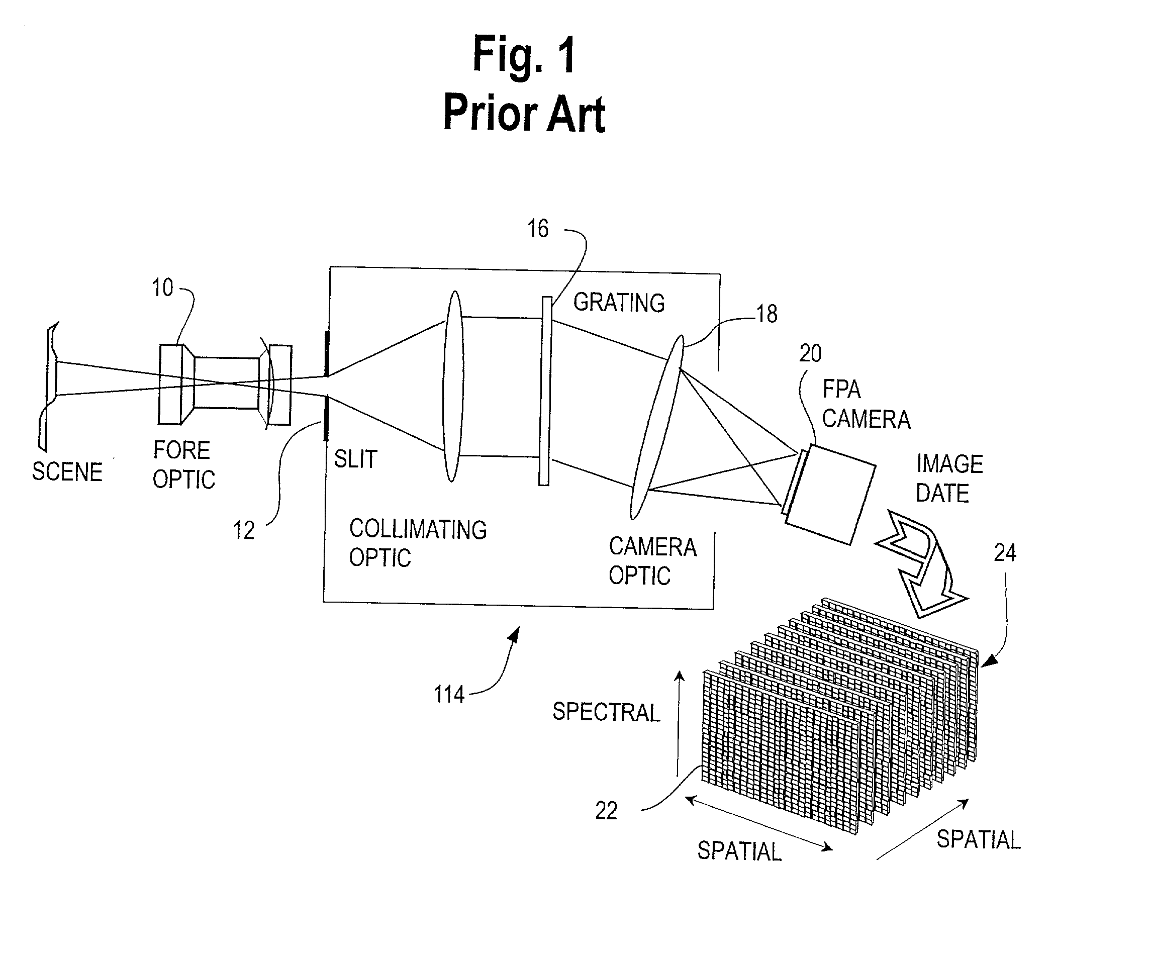
It is commonly recognized that systems such as HIRIS have the limitations of limited resolution, limited exposure time and spatial smearing.
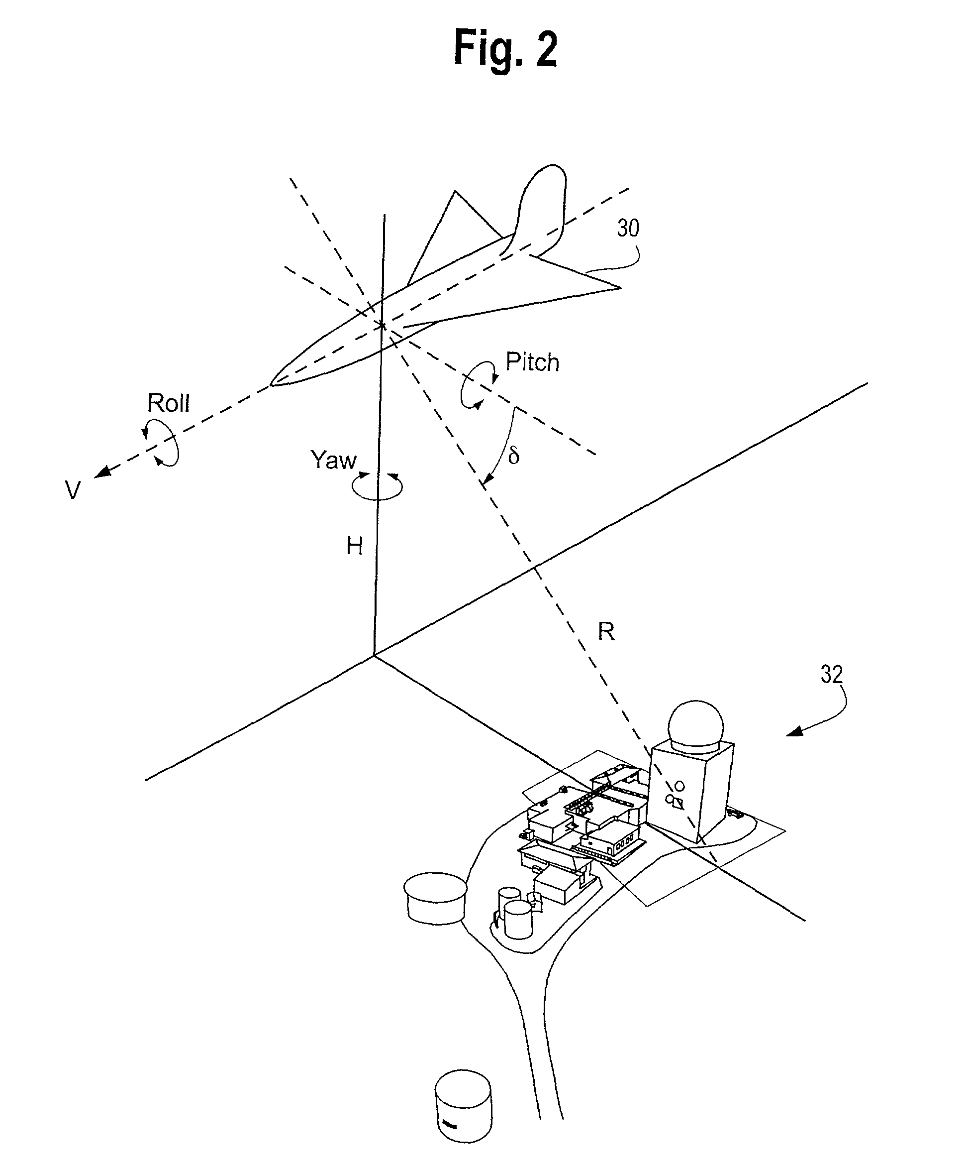
This is highly undesirable and unusable for applications in high-speed reconnaissance aircraft, particularly in a military reconnaissance situation.

Method used


Image

  • Multispectral or hyperspectral imaging system and method for tactical reconnaissance
  • Multispectral or hyperspectral imaging system and method for tactical reconnaissance
  • Multispectral or hyperspectral imaging system and method for tactical reconnaissance

Examples


first embodiment

[0067] A second alternative embodiment of this invention is disclosed which takes maximum advantage of the surface area of a silicon detector array to maximize the number of hyperspectral bands detected by varying the number of TDI columns for each of the sub-arrays according to the a priori knowledge of the spectral response of the Silicon detector material used in the fabrication of the array. Creating sub-arrays with shorter TDI columns in the higher responsivity wavelengths serves to vary the length of the columns of each sub array so as to normalize the signal response of the array to the spectral information and maximize the number of hyperspectral bands detected. Shortening the physical length of the TDI columns for some of the sub-arrays does not limit the user to clocking those sub-arrays to less TDI required according to the invention.

[0068] A third alternative embodiment of the invention varies the TDI coefficients, that is, the number of pixels through which the charge i...

fifth embodiment

[0070] the invention utilizes independent clocking control of specific TDI sub-arrays to provide enhancement in a specific spectral band or group of bands. For example, for some targets, certain specific spectral bands are associated with specific targets (such as particular bands associated with the emissions from a chemical weapons plant), and the array is programmed or designed to increase the signal collection (number of rows of TDI clocking) for those sub-arrays imaging in the portions of the spectrum corresponding to these targets, perhaps at the expense of other portions of the array. The purpose of this embodiment is to increase the ability of the array to detect targets with a characteristic spectral signature. The incident energy may be more efficiently collected in the spectral regions of known targets using this technique. In other words, the capability may be used to locate targets exhibiting certain spectral attributes. These attributes are designed to be imaged with g...


PUM


Abstract

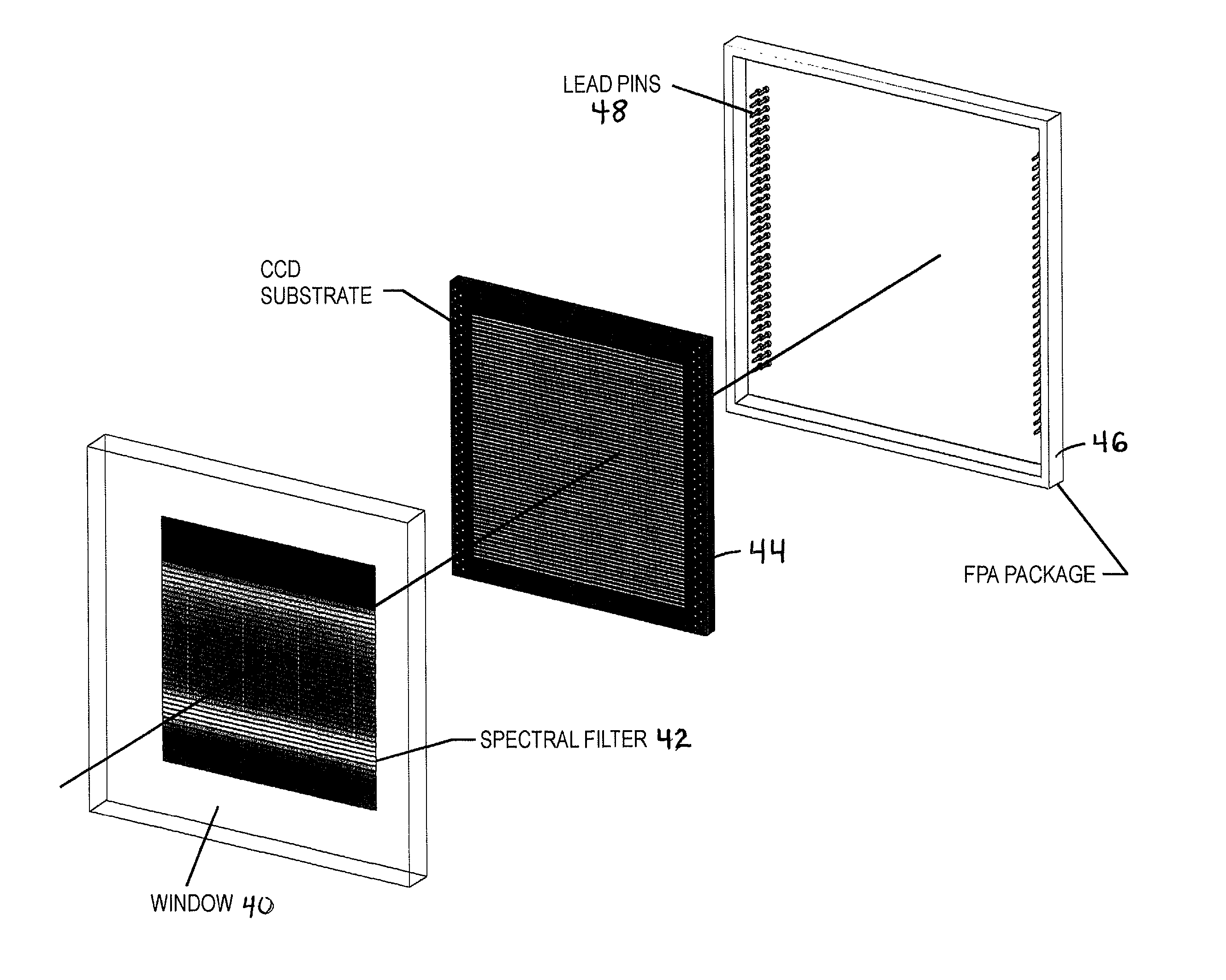
A two-dimensional focal plane array (FPA) is divided into sub-arrays of rows and columns of pixels, each sub-array being responsive to light energy from a target object which has been separated by a spectral filter or other spectrum dividing element into a predetermined number of spectral bands. There is preferably one sub-array on the FPA for each predetermined spectral band. Each sub-array has its own read out channel to allow parallel and simultaneous readout of all sub-arrays of the array. The scene is scanned onto the array for simultaneous imaging of the terrain in many spectral bands. Time Delay and Integrate (TDI) techniques are used as a clocking mechanism within the sub-arrays to increase the signal to noise ratio (SNR) of the detected image. Additionally, the TDI length (i.e., number of rows of integration during the exposure) within each sub-array is adjustable to optimize and normalize the response of the photosensitive substrate to each spectral band. The array provides for parallel and simultaneous readout of each sub-array to increase the collection rate of the spectral imagery. All of these features serve to provide a substantial improvement in the area coverage of a hyperspectral imaging system while at the same time increasing the SNR of the detected spectral image.

Description

[0001] A. Field of the Invention[0002] This invention relates generally to hyperspectral and mutispectral imaging systems for aerial reconnaissance and surveillance applications using a wafer-scale Focal Plane Array (FPA) of an area array format. In this art, "hyperspectral" imaging systems refer to those in which radiation at thirty or more discrete wavelengths are imaged. Imagers that image a lesser but plural number of spectral bands are referred to as "multispectral" imagers. Such systems are used in various applications, including Department of Defense satellite systems and commercial land resource management imaging systems.[0003] The invention further relates to a scanning method for directing a spectrally separated image of the object under surveillance over the FPA in a predetermined direction and rate. In another aspect, the invention further relates to a time delay and integrate (TDI) clocking technique in which the FPA is separated into discrete sub-arrays, in which the ...

Claims


Application Information

Patent Timeline
IPC IPC(8): G01J3/02G01J3/28G01J3/51H04N5/353H04N5/357H04N5/369
CPCG01J3/02G01J3/0256G01J3/2803H04N5/3743G01J3/51H04N3/1525H04N5/37206G01J3/2823H04N25/53H04N25/711H04N25/768H04N25/135
Inventor LAREAU, ANDRE G.SPEER, BRADFORDPFISTER, WILLIAM R.BERAN, STEPHEN R.SWARTZ, BARRYKARINS, JAMES P.LINTELL, ROBERT J.WARREN, CHRISTOPHER P.
Owner THE BF GOODRICH CO
Why Eureka
Eureka Blog
Learn More