Data redundancy methods and apparatus

a data redundancy and data technology, applied in the field of data redundancy methods and apparatuses, can solve the problems of inability to conduct essential business or critical operations, the importance of preserving data integrity and ensuring 24.times.7 continuous access to critical information cannot be overstated, and the downtime is extremely costly

Inactive Publication Date: 2003-10-16
TANDBERG DATA
View PDF9 Cites 63 Cited by
  • Summary
  • Abstract
  • Description
  • Claims
  • Application Information

AI Technical Summary

Problems solved by technology

With the explosive growth in the Internet and mission-critical applications, the importance of preserving data integrity and ensuring 24.times.7 continuous access to critical information cannot be overstated.
Downtime is extremely costly.
Customers, vendors, employees, and prospects can no longer conduct essential business or critical operations.
There is a "lost opportunity" cost to storage failures as well in terms of business lost to competitors.
However, the claims are mostly unrealistic when examined.
Many Information Technology managers are aware that disk drives fail with great frequency.
If more than one drive in a RAID array fails, however, or a service person accidentally removes the wrong drive when attempting to replace a failed drive, the entire RAID storage system becomes inoperable.
And the likelihood of multiple drive failures in large disk arrays is significant.
The resultant cost of inaccessibility to mission-critical information can be devastating in terms of lost opportunity, lost productivity and lost customers.
Accidents can contribute to multiple drive failures in RAID storage.
Service personnel have been known to remove the wrong drive during a replacement operation, crashing an entire RAID storage system.
In poorly engineered RAID systems, replacing a failed drive can sometimes create a power glitch, damaging other drives.
General data center administrative and service operations also present opportunities for personnel to inadvertently disable a drive.
It is well known that the likelihood of a drive failure increases as more drives are added to a disk RAID storage system.
The consequences of a multiple-drive failure can be devastating.
Typically, if more than one drive fails, or a service person accidentally removes the wrong drive when attempting to replace a failed drive, the entire RAID storage system is out of commission.
Access to critical information is not possible until the RAID system is re-configured, tested and a backup copy restored.
Thus, the possibility of a multiple-drive failure is very high for mission-critical applications that run 24-hours daily on a continuous basis.
Moreover, the larger a RAID storage system, the greater the potential of suffering multiple-drive failures.
While RAID-0 delivers high performance, it cannot sustain even a single drive failure because there is no parity information or data redundancy.
Although the most costly, mirroring data on separate drives (RAID-1), means that if one drive fails, critical information can still be accessed from the mirrored drive.
Typically, RAID-1 involves replicating all data on two separate "stacks" of disk drives on separate SCSI channels, incurring the cost of twice as many disk drives.
There is a performance impact as well, since data must be written twice, consuming both RAID system and possibly server resources.
With the exception of costly RAID-1 (or combinations of RAID-1 with RAID-0 or RAID-5) configurations, there have been few solutions for recovering from a multiple drive failure within a RAID storage system.
Even the exceptions sustain multiple drive failures only under very limited circumstances.
Combining striping and parity within mirrored stacks buys some additional capabilities, but is still subject to these drive-failure limitations.
In addition, the subject matter in U.S. Pat. No. 5,271,012 ("Method and Means for Encoding and Rebuilding Data Contents of up to Two Unavailable DASDs in an Array of DASDS" and in U.S. Pat. No. 5,333,143 ("Method and Means for B-Adjacent Coding and Rebuilding Data from up to Two Unavailable DASDs in a DASD Array") address multiple failures, but are limited.
This leads to read inefficiency unless a rotation structure is superimposed on the formula, in which case it leads to algorithmic inefficiency.
Moreover, because these algorithms have exceptionally fast computational speeds, storage transfer rate performance actually increases while adding virtually unlimited data protection.
(Here, "similar" means their raw data storage capability is the same when all organized by one chunk size, but the devices themselves may be physically dissimilar.)
(The same approach will work for deads that are not together, but is more complicated to visualize.)

Method used


Image

  • Data redundancy methods and apparatus
  • Data redundancy methods and apparatus
  • Data redundancy methods and apparatus

Examples


Embodiment Construction

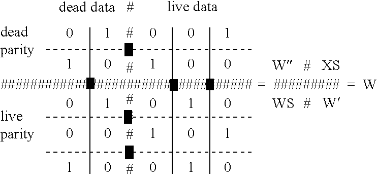
[0175] Matrix multiplication modulo 2 is used. # is not a number, but a separator between dead and live territory. 11 W 01 #001 10 #100 # # # # # # 01 #010 00 #101 10 #010 D 1 0 # 1 1 1 = P 1 0 # 1 0 0= P ' ' # # # P3

[0176] D" and P" are lost. D' and P3=P' mare known, as is W. 12 W ' D ' P 1 010 1 1 101 1 = 0 010 1 1 P 1^P 3 P 2 1 1 0 0 0 = 0 1 0 1 W S J S 01 001 00 solution = 100 10 J S P 2 D ' ' 001 0 1 100 0 = 0 1

[0177] And thus, D" is recovered. P" can be recovered by encoding from D" and D'.

[0178] Detection of Burst Errors. The following discussion relates to a technique for error detection with use of a matrix parity coding technique. Coding matrices useful for error detection according to this technique include near-Wiencko matrices, Wiencko matrices as described in U.S. patent application Ser. No. 09 / 366,222 referenced above, and any other suitable coding matrices, which are generally referred to simply as "coding matrix" or "coding matrices" in the following description. Co...


PUM

PropertyMeasurementUnit
Mean Time Between Failureaaaaaaaaaa
frequencyaaaaaaaaaa
timeaaaaaaaaaa

Abstract

Method and apparatus for providing data recovery in a one or multiple disk loss situation in a RAID5 like system. A data storage apparatus has a plurality of n disks storing data comprising a plurality of n data groupings stored across the plurality of n disks. Each one of the n data groupings comprises a data portion and a redundancy portion. The size of the data portion relative to the redundancy portion is as H to Q, where H / Q<(n-m) / m, where m is the maximum number of disks that may be lost at any given time. Advantageously, the n data portions are recoverable from any and all combinations of n-m data grouping(s) on n-m disk(s) when the other m data grouping(s) are unavailable, where 1<=m<n.

Description

[0001] This application is a continuation-in-part of U.S. patent application Ser. No. 09 / 366,222, filed Aug. 12, 1999, now allowed, which is herein incorporated by reference in its entirety.INCORPORATION BY REFERENCE[0002] Incorporated by reference herein are Appendix A and Appendix B, which are submitted on a compact disc and contain computer printouts and / or program listings. The compact disc contains the following files:[0003] (1) Name of file: APNDXA.TXT; date of creation: Feb. 12, 2003; size: 3 KB;[0004] (2) Name of file: DIFICUL.C; date of creation: Sep. 25, 2000; size: 8 KB;[0005] (3) Name of file: MAKEFILE; date of creation: Feb. 19, 2003; size: 1 KB;[0006] (4) Name of file: NEARW.C; date of creation: Oct. 11, 2001; size: 12 KB;[0007] (5) Name of file: NEARW.COD; date of creation: Feb. 7, 2003; size: 5 KB;[0008] (6) Name of file: NEARWLIB.C; date of creation: Oct. 11, 2001; size: 17 KB; and[0009] (7) Name of file: NEARWLIB.H; date of creation: Oct. 11, 2001; size: 5 KB.[0010...

Claims


Application Information

Patent Timeline
Patent Type & Authority Applications(United States)
IPC IPC(8): G06F11/10G11B20/18H03M13/47
CPCG06F11/1076G11B20/1803G06F11/1088G06F2211/1059G06F2211/1009H03M13/47
Inventor DICKSON, LAWRENCE JOHN
Owner TANDBERG DATA
Why Eureka
Try Eureka