Eureka AIR delivers breakthrough ideas for toughest innovation challenges, trusted by R&D personnel around the world.

Thread tension regulation in a thread brake device and method in a textile processing machine

Inactive Publication Date: 2003-10-23
LINDAUER DORNIER GMBH
View PDF11 Cites 0 Cited by
  • Summary
  • Abstract
  • Description
  • Claims
  • Application Information

AI Technical Summary

Benefits of technology

[0012] The new basic principle for achieving a controlled thread braking effect according to the invention is that the thread tension is applied or caused by the brake element and is simultaneously measured directly on the brake element (via the reaction force or counter force that is exerted by the thread onto the brake element). In this manner, the braking force of the brake element applied to the thread can be regulated dependent on and responsive to the thread tension. The thread tension is measured directly by the reaction force exerted on the brake element by the thread, so that a separate thread tension sensor is no longer necessary.
[0016] The controllable actuator element acting on at least one of the force application elements may also preferably be embodied as a piezoelectric actuating element. Such a piezoelectric actuating element is able to carry out very rapid actuating motions. Thus, the selective variable application of the braking force onto the thread can be very rapidly adjusted dependent on and responsive to the reaction force that is measured in the above described manner. In effect, the inventive arrangement provides a very rapidly acting feedback loop of the force information, which allows a rapid regulation of the braking force and the resulting thread tension.

Problems solved by technology

Unfortunately, in all of the known arrangements, the separate thread tension sensor requires the thread to be deflected around a suitable measuring element in order to be able to measure the actual presently existing thread tension, which is representative of or associated with the applied braking force.
The use of such a thread tension sensing arrangement is disadvantageous, because the necessary additional deflection of the thread also causes an additional mechanical loading of the thread, which is undesirable and unnecessary.

Method used


Image

  • Thread tension regulation in a thread brake device and method in a textile processing machine
  • Thread tension regulation in a thread brake device and method in a textile processing machine
  • Thread tension regulation in a thread brake device and method in a textile processing machine

Examples


Embodiment Construction

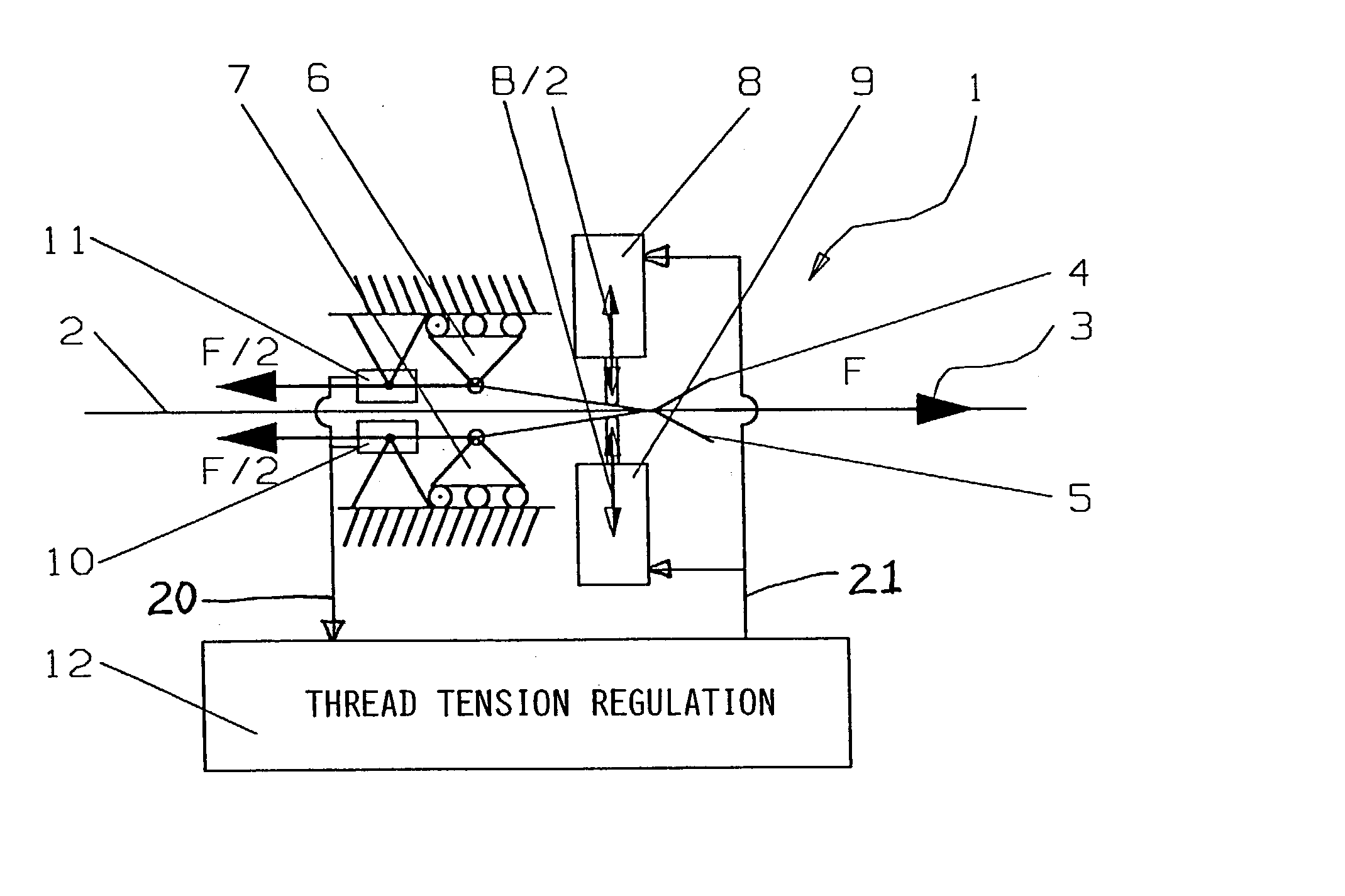
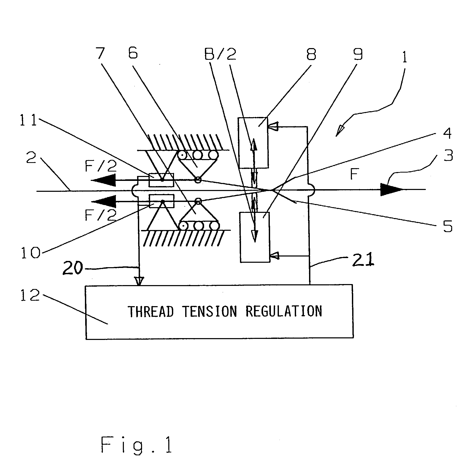
[0020] FIG. 1 schematically shows a thread brake arrangement 1 according to the invention, as it may be used for braking a weft thread in a weaving loom. The thread 2 is guided and extends in a threading running or feed direction 3 along a straight linear thread travel path through the thread brake arrangement 1. The thread brake arrangement 1 includes two lamellar brake elements 4 and 5, for example thin metal sheets or lamellae 4 and 5, which are elastically flexible and elastically pressed against one another, with the thread 2 received running therebetween. The thread brake arrangement 1 further includes two opposed actuators or operating elements 8 and 9 that selectively act on the two lamellar brake elements 4 and 5 in opposite directions as shown by the double-headed arrows, to apply a controllable actuating displacement and / or force to the brake elements 4 and 5, so as to exert a controllable braking force B via the brake elements 4 and 5 onto the thread 2.

[0021] When the th...


PUM


Abstract

A thread brake arrangement for use in a textile processing machine includes two brake elements with the thread running therebetween. An actuator, preferably a piezoelectric actuator, variably actuates one of the brake elements relative to the other to exert an adjustable braking force onto the thread. The thread exerts a reaction force in the thread running direction onto the brake elements. At least one of the brake elements is movably supported to be movable along the thread running direction, and is mechanically coupled to a force transducer that measures the reaction force, which is proportional or equal to the thread tension force. A regulating arrangement receives the measured force signal, and controls the actuator to adjust the adjustable brake element, so as to vary the applied braking force and thus regulate the arising thread tension responsive to and dependent on the measured reaction force.

Description

PRIORITY CLAIM[0001] This application is based on and claims the priority under 35 U.S.C. .sctn.119 of German Patent Application 102 18 059.8, filed on Apr. 23, 2002, the entire disclosure of which is incorporated herein by reference.[0002] The invention relates to an apparatus and a method for regulating the thread tension in connection with selective braking of the thread in a textile processing machine, especially in a weaving loom.BACKGROUND INFORMATION[0003] Such devices pertinent to the general background of the present invention, often known as thread brakes, are well known in many different conventional configurations and arrangements, and are typically used, for example, as weft thread brakes in weaving looms.[0004] German Patent 34 46 567 and corresponding U.S. Pat. No. 4,641,688 disclose a weft thread brake with a controllable braking effect. This known weft thread brake comprises two lamellar brake elements that are arranged opposite each other and press against each oth...

Claims


Application Information

Patent Timeline
IPC IPC(8): B65H59/24D03D47/27D03D47/34
CPCB65H59/24B65H2515/31B65H2515/34B65H2701/31D03D47/34B65H2220/01B65H2220/02
Inventor HERRLEIN, WILHELMRENZ, MANUEL
Owner LINDAUER DORNIER GMBH
Why Eureka
Eureka Blog
Learn More