Positional control of a controlled object during movement initiation

a technology of control object and movement, applied in the direction of electric programme control, program control, instruments, etc., can solve the problems of insufficient compensation at time t2, inability to effectively reduce the tracking deviation, and no improvement in the initial tracking deviation x-xl at times t1

Inactive Publication Date: 2003-10-30
OKUMA CORP
View PDF6 Cites 27 Cited by
  • Summary
  • Abstract
  • Description
  • Claims
  • Application Information

AI Technical Summary

Benefits of technology

0033] FIG. 7 is a timing chart for explaining an example operation of the positional control device of FIG. 5.

Problems solved by technology

As a result, with the conventional initial friction compensation, there is no improvement in the initial tracking deviation X-xL at times t1 and t3.
On the contrary, when Vsfco is set such that the tracking deviation at time t4 is favorably reduced, compensation is not sufficiently executed at time t2, failing to effectively reduce the tracking deviation.
Accordingly, it is disadvantageous in that the instances at which the friction compensation operations are performed do not match the instances at which axis movement delays due to static friction actually occur.
In addition, even when a friction compensation operation is performed at a proper point, compensation tends to be either excessive or insufficient because the initial friction compensation value is determined without taking into account the generated torque X value of the servo motor during the standstill state.
Another problem is that no measures are taken with respect to the tracking deviation generated due to a difference in magnitude between static friction and kinetic friction.
As such, the initial friction compensation function of a conventional positional control device cannot satisfactorily accomplish the original object of initial friction compensation, which is to reduce a movement delay due to friction during a movement initiation, by generating a friction compensation value having appropriate direction and magnitude at an instance when the movement delay occurs, such that positional deviation X-xL at the initiation of movement is minimized.

Method used


Image

  • Positional control of a controlled object during movement initiation
  • Positional control of a controlled object during movement initiation
  • Positional control of a controlled object during movement initiation

Examples


Embodiment Construction

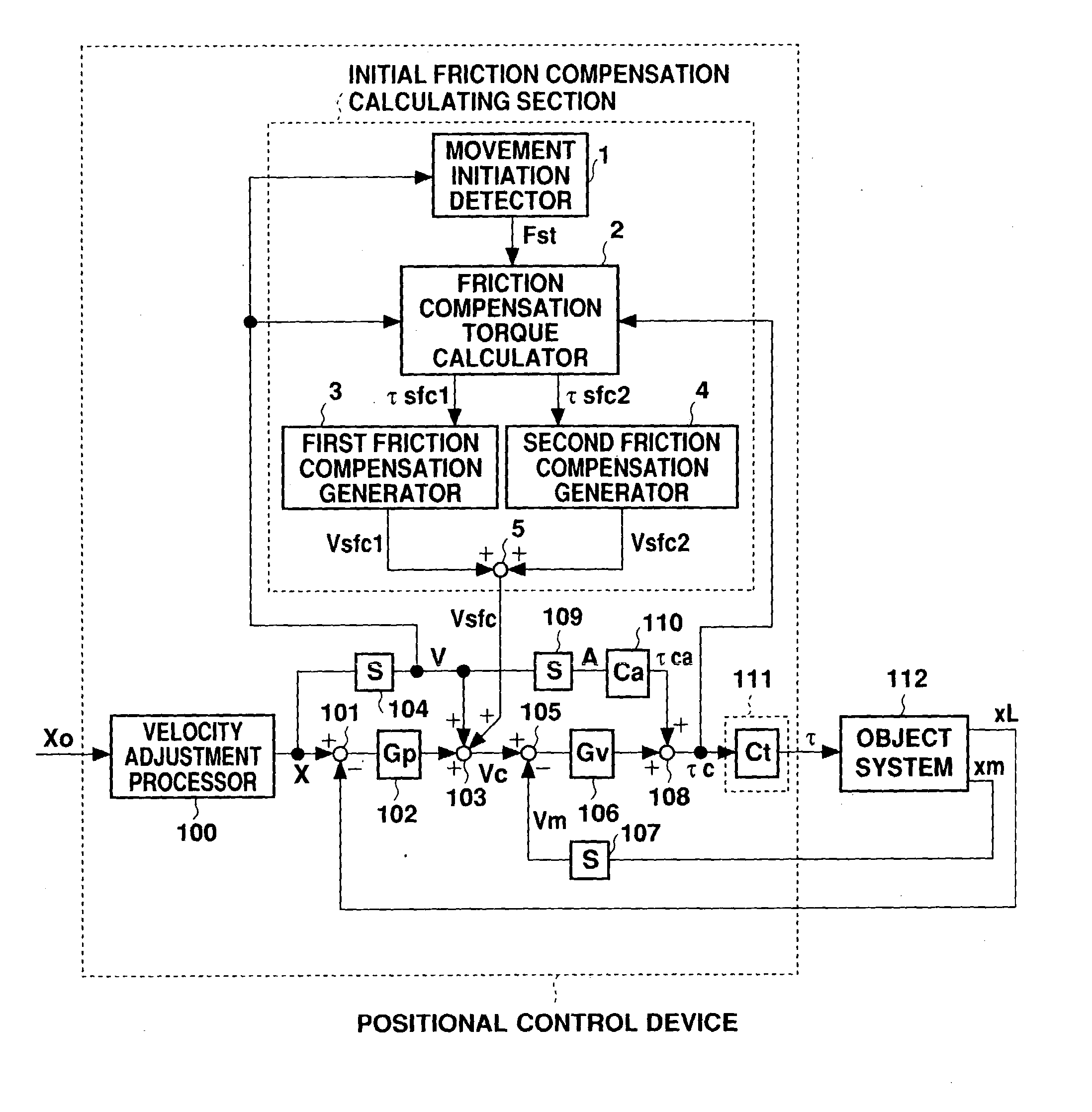
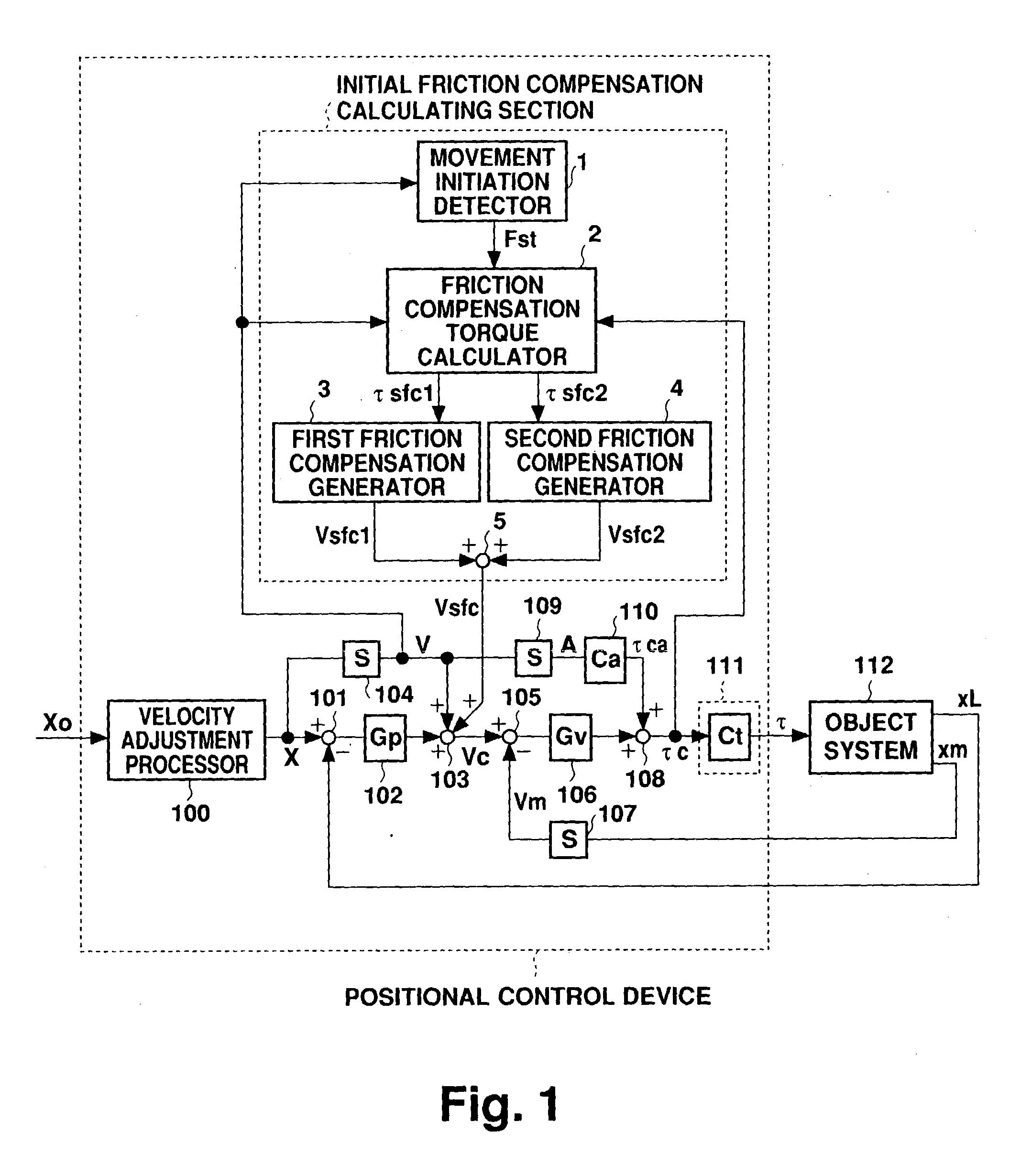
[0034] FIG. 1 is a block diagram showing a first example configuration of a positional control device according to a preferred embodiment of the present invention. In the positional control device of FIG. 1, components identical to those described above in relation to FIG. 5 are labeled with the same names and reference numerals, and explanation of those components will not be repeated in this section. The initial friction compensation calculating section according to the present invention is described as follows. A movement initiation detector 1 receives input of a velocity command value V, and outputs an initiation detection signal Fst. Fst is a binary signal indicating either ON or OFF, in which ON is output in a form of a pulse according to (8).

Fst:ON (when V=0V>0 or V=0V<0) (8)

[0035] A friction compensation torque calculator 2 receives the movement initiation detection signal Fst, and outputs two friction torque compensation values .tau.sfc1 and .tau.sfc2 determined by equation...


PUM


Abstract

In a positional control device for controlling a position of a controlled object using a motor, when generating a torque command value tauc which serves as the command value for the servo motor of the controlled object system (112), a friction compensation value for use when the controlled object initiates a movement is calculated based on a velocity command value V and a torque command value tauc determined according to a positional command value Xo supplied from a superordinate device. More specifically, an initial friction compensation calculating section calculates a torque compensation amount Vsfc1 corresponding to a difference between torque being generated during the standstill state and torque required by the controlled object to initiate the movement, and a torque compensation amount Vsfc2 corresponding to an amount of change in friction that occurs during a transition from static friction to kinetic friction in a period immediately before and after initiation of the movement. Vsfc1 and Vsfc2 are then used to calculate compensated values of the torque command value tauc. Positional tracking deviation generated due to friction during a movement initiation can thereby be reduced, regardless of operational conditions during the standstill state or of the movement direction and velocity effected thereafter.

Description

[0001] 1. Field of the Invention[0002] The present invention relates to a positional control device which controls a position of an object in accordance with a command from a superordinate device, and more particularly to control of a controlled object during initiation of movement.[0003] 2. Description of the Related Art[0004] FIG. 5 is a block diagram showing one example of a conventional full closed positional control device (hereinafter referred to simply as a positional control device). The positional control device controls the position of an object system 112 comprising a movable member, such as a table, connected via a coupling with a servo motor (not shown) serving as the drive motor for enabling movement. The configuration and operation of the positional control device are explained as follows. The positional control device receives input of a positional command value Xo from a superordinate device (not shown). A velocity adjustment processor 100 executes velocity adjustme...

Claims


Application Information

Patent Timeline
Patent Type & Authority Applications(United States)
IPC IPC(8): G05D3/12G05B19/404H02P29/00
CPCG05B2219/41154G05B19/404
Inventor EGUCHI, SATOSHI
Owner OKUMA CORP
Why Eureka
Try Eureka