Electrical heating apparatus

a technology of electric heating apparatus and heating element, which is applied in the direction of lighting and heating apparatus, process and machine control, instruments, etc., can solve the problems of increasing the time and cost of installing such electrical heating apparatus, as well as the time for disassembly, and achieves the effect of convenient maintenance and repair and faster installation

Inactive Publication Date: 2003-11-06
ATMOR IND LTD
View PDF0 Cites 13 Cited by
  • Summary
  • Abstract
  • Description
  • Claims
  • Application Information

AI Technical Summary

Benefits of technology

[0004] An object of the present invention is to provide electrical heating apparatus which enables faster installation, as well as more convenient maintenance and repair, of the apparatus.
[0007] Such a construction greatly facilitates installation, maintenance and repair of the apparatus.
[0009] In some of the described embodiments, the apparatus further comprises a control valve for controlling the water flow into the electrical heater; the control valve including a housing having an inlet also integrally formed with the inlet conduit and with at least part of the control valve housing, thereby further facilitating installation, maintenance and repair of the apparatus. Several embodiments are described below in which the control valve is a manually presettable valve, particularly a ball valve having a ball rotatable within the control valve housing and formed with a variable-depth passageway for controlling the water flow therethrough to the electrical heater. In other described embodiments, the control valve is a regulator valve automatically regulating the water flow therethrough to have a relatively constant rate despite variations in the water inlet pressure.
[0012] Other embodiments of the invention are described below wherein the pressure-responsive device senses the flow rate through it to control the energization of the electrical heater. In the described preferred embodiments, the pressure-responsive device senses the flow rate by sensing the difference in pressure at the inlet and outlet of the pressure-responsive device. Thus, if the pressure difference is substantially zero, this indicates that there is no flow through that device, and therefore it will not energize the electrical heater; whereas if the pressure difference is significant, this will indicate flow through the device, and therefore the device will energize the electrical heater.
[0015] According to a still further aspect of the present invention, there is provided a regulating valve comprising a housing; a membrane within the housing; and a stem within the housing having a head of convex configuration facing the membrane but normally spaced therefrom to define a flow-control passageway; the convex configuration of the stem head producing, with the membrane, different cross-sectional areas and thereby different flow rates in the control passageway, creating differential pressures acting on the membrane tending to deform the membrane such as to maintain a relatively constant flow rate through the flow control passageway despite variations in water inlet pressure.

Problems solved by technology

Producing the foregoing components as separate units increases the time and cost of installing such an electrical heating apparatus, as well as the time for disassembling the apparatus for purposes of maintenance and / or repair.

Method used


Image

  • Electrical heating apparatus
  • Electrical heating apparatus
  • Electrical heating apparatus

Examples


Embodiment Construction

[0026] The Embodiment of FIGS. 1 and 2

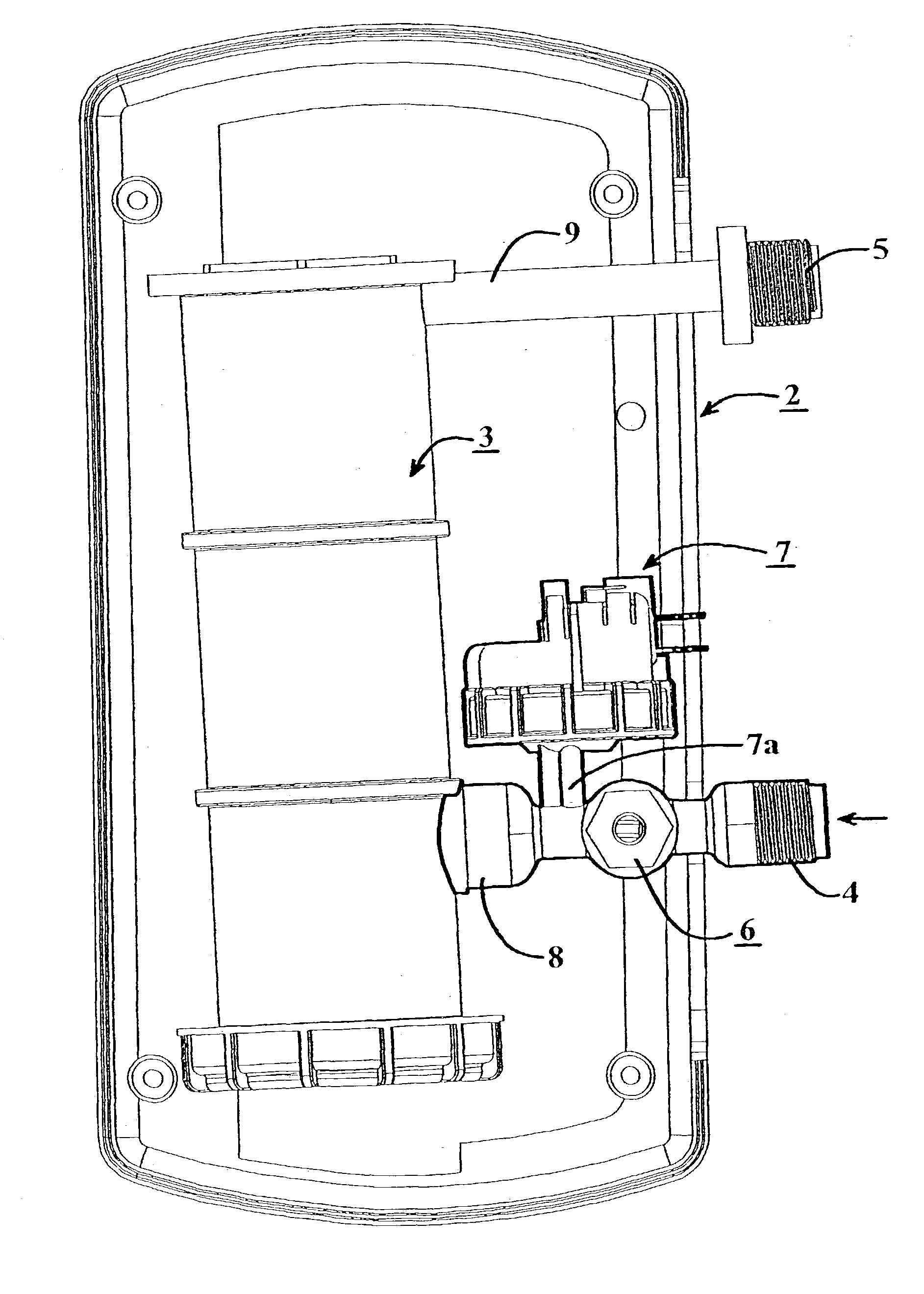
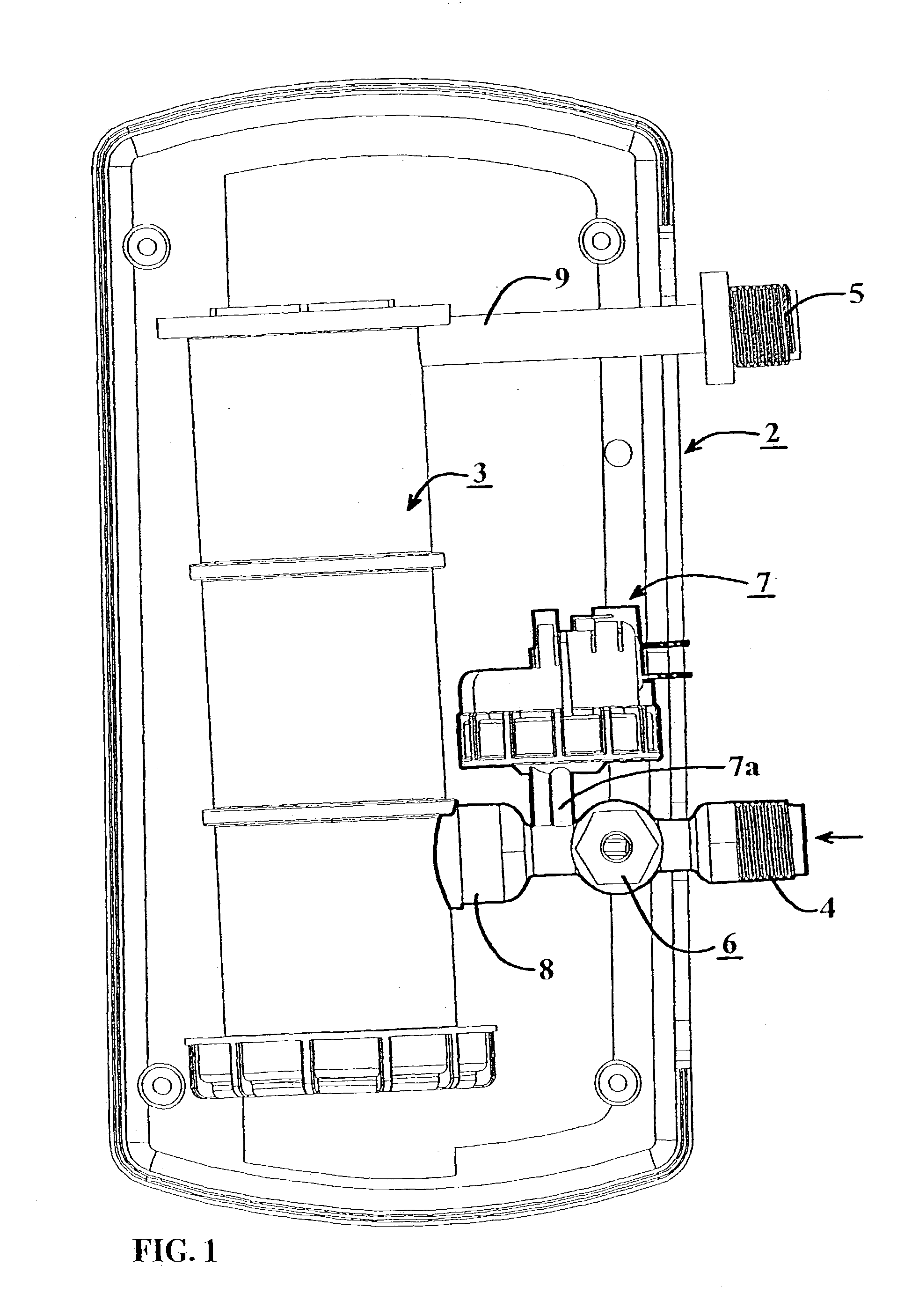
[0027] FIG. 1 illustrates the overall arrangement of one form of electrical heating apparatus constructed in accordance with the present invention. The illustrated apparatus includes a housing 2 containing an electrical heater 3 for automatically, and substantially instantaneously, heating water passing through the electrical heater from a cold water supply pipe to a hot water delivery pipe. An inlet conduit 4 is connectable between the water supply pipe (not shown) and the electrical heater 3 for inletting cold water into the electrical heater, and an outlet conduit 5 is connectable between the electrical heater 3 and the water delivery pipe (not shown) for outletting hot water thereto from the electrical heater.

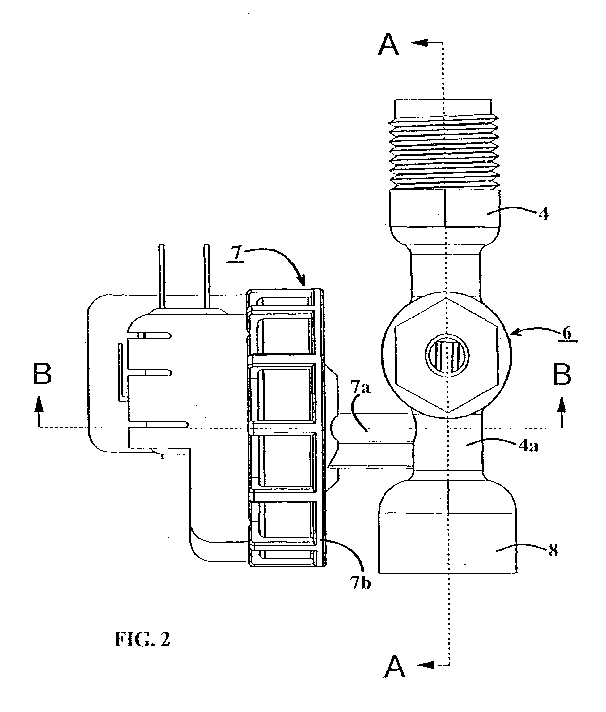
[0028] The heating apparatus illustrated in FIG. 1 further includes a control valve 6 which controls the supply of the water to the electrical heater 3, a pressure-responsive device 7 which cooperates with one or more electrical switche...


PUM


Abstract

Electrical heating apparatus includes an electrical heater in which the inlet conduit for inletting cold water to the electrical heater and / or the outlet conduit for outletting hot water thereto from the electrical heater is integrally formed with a pressure-responsive device which senses the flow rate to or through the electrical heater to control the energization of the electrical heater. The apparatus also includes a regulating valve constituted of a membrane and a stem having a head of convex configuration facing the membrane but normally spaced therefrom to define a flow-control passageway which creates differential pressures acting on the membrane tending to deform the membrane such as to maintain a relatively constant flow rate through the flow control passageway despite variations in water inlet pressure.

Description

FIELD AND BACKGROUND OF THE INVENTION[0001] The present invention relates to electrical heating apparatus, and particularly to such apparatus for automatically heating water passing through the apparatus from a cold water supply pipe to a hot water delivery pipe.[0002] Electrical heating apparatus of the foregoing type is widely used for providing instantaneous hot water from a cold water supply, such as for preparing a hot beverage, taking a hot shower, washing dishes, etc. Such apparatus generally includes a housing having an electrical heater, one or more electrical switches controlling the electrical heater, an inlet conduit connectable between the water supply pipe and the electrical heater for inletting cold water to the electrical heater, a pressure-responsive device cooperable with the electrical switches to control the electrical heater, a heater coupling for inletting the water into the electrical heater, and an outlet conduit connectable between the electrical heater and ...

Claims


Application Information

Patent Timeline
Patent Type & Authority Applications(United States)
IPC IPC(8): F24H9/20G05D7/01H01H35/26
CPCF24H9/2028H01H35/2657G05D7/012G05D7/0113F24H15/37F24H15/219F24H15/174
Inventor HADAR, YORAM
Owner ATMOR IND LTD
Why Eureka
Try Eureka