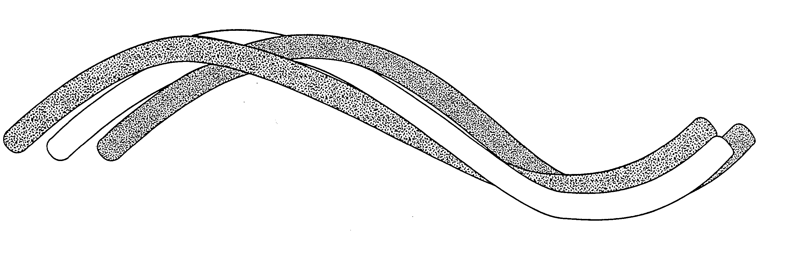
Functional fibers and fibrous materials
a technology of functional applied in the field can solve the problems of difficult and expensive to make fibers comprised of more than one type of continuous fiber using the process, and the physical and chemical properties of fibers and fibrous materials cannot be precisely tuned to particular applications
- Summary
- Abstract
- Description
- Claims
- Application Information
AI Technical Summary
Problems solved by technology
Method used
Image

Examples
example 1
6.1. Example 1
[0086] Wicking Device for Water
[0087] The fiber material comprised T-202 (CoPET / PET, weight ratio was about 50 to 50) staple fiber, manufactured by Fiber Innovation Technology Inc, Johnson City, Tenn., and Tencel.RTM., manufactured by Acordis Cellulosic Fibers Inc, Axis, Ala. The staple fiber diameter of T-202 was 3 dpf and length was 1.5 inches. The staple fiber diameter of Tencel.RTM. was 3 dpf, and length was 1.5 inches. The material was blended and carded in John D. Hollingsworth on Wheels, Inc., Greenville, S.C. Three tests were carried out. For each formulation, three slivers (bundles) of fiber material with total size of 110, 120 and 130 g / yard, respectively, were introduced into the heating zone of an oven. Oven was 70 inches in length, 9.5 inches in width, and 15 inches in depth. The oven processing temperature was 200.degree. C., the die control temperature was 90.degree. C., and the pulling rate was 4 inches / min. The resulting functional fibrous material was...
example 2
6.2. Example 2
[0090] Wicking Device for Ink
[0091] The binder fiber was T-202 with 3 dpf in size and 1.5 inches in length. The functional fibers were Tencel.RTM. and rayon-6150, respectively. The permanent marker nib formulation was pure T-202, and there were two formulations for dry erase marker nibs, Tencelo / T-202 and rayon-6150 / T-202. The oven processing temperature was 210.degree. C., the die control temperature was 100.degree. C., and the pulling rate was 4 inches / minute. The die cross section was 3.7 mm in height and 5.7 mm in width. The cooled composites rectangular rods were cut into wedge shaped marker nibs of 40 mm in length.
[0092] An alcohol based dry erase marker ink was used to test the fiber composite ink wicking property. The test writing machine was made by Hutt, Germany. The machine was designed for pen writing on test paper. When the dry erase marker nibs were tested, the machine was modified by replacing writing paper with whiteboard covering with a non-osmotic sm...
example 3
6.3. Example 3
[0094] Activated Nylon for Biomolecule Immobilization
[0095] Staple nylon fiber was mixed with staple binder fiber, and the mixture was carded into slivers. Fiber slivers were sintered in a heated oven to make fibrous rods. The sintered fibrous rods were cut into suitably sized samples, and then nylon fiber component in the samples was activated by alkylating reagent. The alkylated nylon components were used to immobilize protein, or modified by subsequent chemical methods, such as thiol functionalization, hydrazine functionalization, and aldehyde functionalization agents.
[0096] 6.3.1. Fiber Component Sintering
[0097] The mixture of fibers comprised 30 percent by weight of staple bicomponent nylon-6 / nylon-6,6, T-270, with size of 3 dpf, and length of 1.5 inches, and 70 percent of staple binder fiber, CoPET / PET, T-202, with size of 3 dpf, and length of 1.5 inches, both manufactured by Fiber Innovation Technology, Inc. The material was mixed and carded in John D. Hollingsw...
PUM
| Property | Measurement | Unit |
|---|---|---|
| density | aaaaa | aaaaa |
| density | aaaaa | aaaaa |
| density | aaaaa | aaaaa |
Abstract
Description
Claims
Application Information
 - R&D
- Intellectual Property
- Life Sciences
- Materials
- Tech Scout
- Unparalleled Data Quality
- Higher Quality Content
- 60% Fewer Hallucinations
Browse by: Latest US Patents, China's latest patents, Technical Efficacy Thesaurus, Application Domain, Technology Topic, Popular Technical Reports.
© 2025 PatSnap. All rights reserved.Legal|Privacy policy|Modern Slavery Act Transparency Statement|Sitemap|About US| Contact US: help@patsnap.com