

Composite material
a technology of composite materials and films, applied in the field of composite materials, can solve the problems of easy peeling of films, deterioration of photocatalyst functions, and insufficient adhesion force between films and substrates
- Summary
- Abstract
- Description
- Claims
- Application Information
AI Technical Summary
Benefits of technology
Problems solved by technology
Method used
Image

Examples
example 1
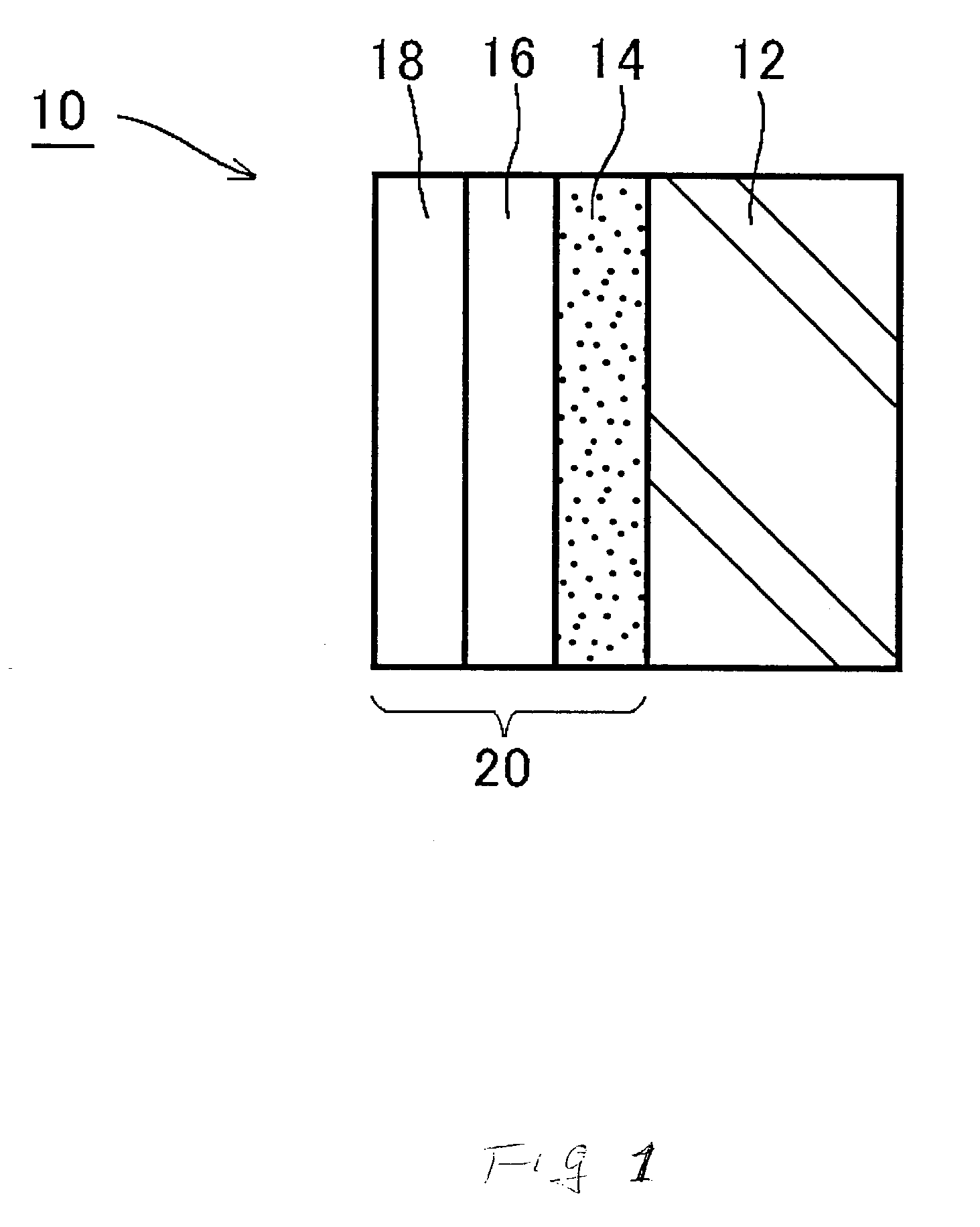
Example of Composite Material 10 shown in FIG. 1: Containing Lanthanoide Oxide in Primer Layer
[0034] Onto glass substrate 12 having been heated to 100.degree. C., a 30 nm thick film of a double oxide comprising La.sub.2O.sub.3 and Al.sub.2O.sub.3 or a mixture of La.sub.2O.sub.3 with Al.sub.2O.sub.3 (La.sub.2O.sub.3 / Al.sub.2O.sub.3 weight ratio=50 / 50) as primer layer 14 making up a layer for suppressing sodium dispersion, a 200 nm thick film of TiO.sub.2 as photocatalyst layer 16 in the state of not serving as photocatalyst, and a 20 nm thick film of SiO.sub.2 as hydrophilic layer 18 were formed by a vacuum deposition method in this order. Thereafter, the laminated film was thermally treated at 500.degree. C. to impart photocatalyst layer 16 to photocatalytic functions. Since primer layer 14 making up a layer for suppressing sodium dispersion is placed between glass substrate 12 and photocatalyst layer 16, dispersion of sodium ions contained in glass substrate 12 during the course of...
example 2
Example of Composite Material 10 shown in FIG. 1: Changing Proportion of Double Oxide or Mixture in Example 1
[0035] Onto glass substrate 12 having been heated to 100.degree. C., a 30 nm thick film of a double oxide comprising La.sub.2O.sub.3 and Al.sub.2O.sub.3 or a mixture of La.sub.2O.sub.3 with Al.sub.2O.sub.3 (La.sub.2O.sub.3 / Al.sub.2O.sub.3 weight ratio=80 / 20) as primer layer 14 making up a layer for suppressing sodium dispersion, a 200 nm thick film of TiO.sub.2 as photocatalyst layer 16 in the state of not serving as photocatalyst, and a 20 nm thick film of SiO.sub.2 as hydrophilic layer 18 were formed by a vacuum deposition method in this order. Thereafter, the laminated film was thermally treated at 500.degree. C. to impart photocatalyst layer 16 to photocatalytic functions. Since primer layer 14 making up a layer for suppressing sodium dispersion is placed between glass substrate 12 and photocatalyst layer 16, dispersion of sodium ions contained in glass substrate 12 durin...
example 3
Example of Composite Material 10 shown in FIG. 1: Changing Lanthanoide in Example 1
[0036] Onto glass substrate 12 having been heated to 100.degree. C., a 30 nm thick film of a double oxide comprising Pr.sub.2O.sub.3 and Al.sub.2O.sub.3 or a mixture of Pr.sub.2O.sub.3 with Al.sub.2O.sub.3 (Pr.sub.2O.sub.3 / Al.sub.2O.sub.3 weight ratio=50 / 50) as primer layer 14 making up a layer for suppressing sodium dispersion, a 200 nm thick film of TiO.sub.2 as photocatalyst layer 16 in the state of not serving as photocatalyst, and a 20 nm thick film of SiO.sub.2 as hydrophilic layer 18 were formed by a vacuum deposition method in this order. Thereafter, the laminated film was thermally treated at 500.degree. C. to impart photocatalyst layer 16 to photocatalytic functions. Since primer layer 14 making up a layer for suppressing sodium dispersion is placed between glass substrate 12 and photocatalyst layer 16, dispersion of sodium ions contained in glass substrate 12 during the course of this therm...
PUM
| Property | Measurement | Unit |
|---|---|---|
| thickness | aaaaa | aaaaa |
| thickness | aaaaa | aaaaa |
| contact angle | aaaaa | aaaaa |
Abstract
Description
Claims
Application Information