Rumble strip cutter

a technology of rumble strip and cutter, which is applied in the direction of manufacturing tools, roads, and highways, can solve the problems of limiting the forward speed of the milling machine, and affecting the cutting effect of rumble strips

Inactive Publication Date: 2003-11-20
MAXWELL JAMES F
View PDF6 Cites 4 Cited by
  • Summary
  • Abstract
  • Description
  • Claims
  • Application Information

AI Technical Summary

Benefits of technology

0006] It is, therefore, an object of the invention to provide a rumble strip milling appara

Problems solved by technology

This coordinated motion severely limits the forward speed of the milling machine.
Typically the forward speed of these rumble strip cutters can he no greater than one or two miles per hour, making the pr

Method used


Image

  • Rumble strip cutter
  • Rumble strip cutter
  • Rumble strip cutter

Examples


example ii

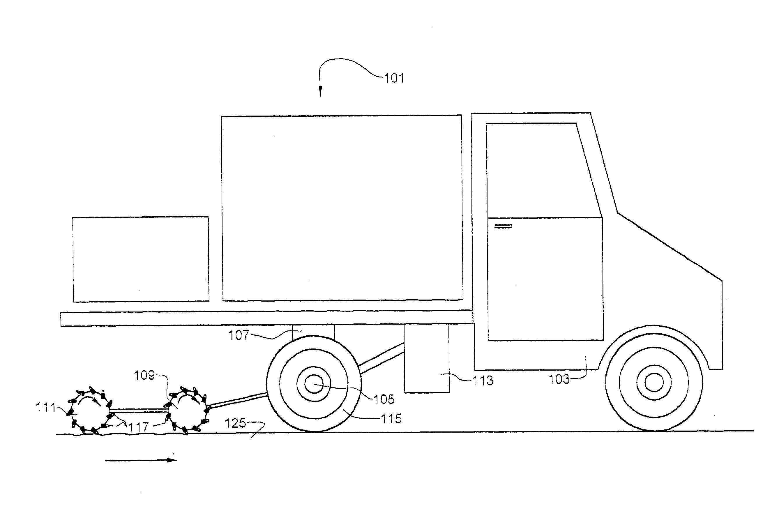
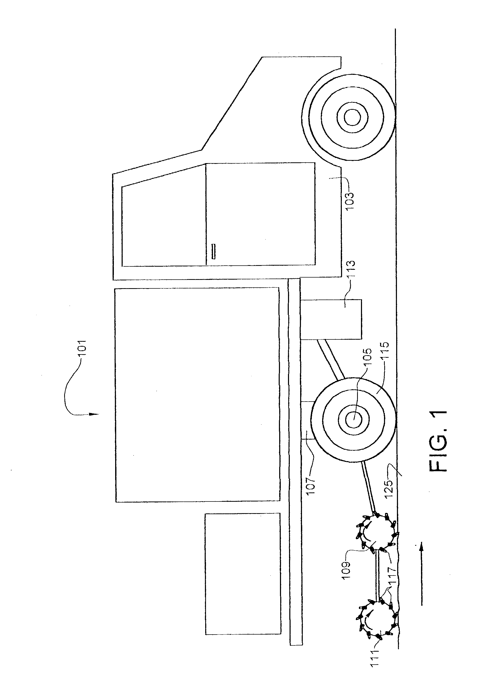
[0042] Reference is now made to FIG. 3, which a schematic diagram of an alternate rumble strip milling machine of the invention 301. A truck 303 with a suitable wheelbase and at least one rear drive axle 305 provides a forward motion to the apparatus. Four cutting wheels 309, 310, 311, 312 are mounted behind the drive axle. The truck is equipped with suitable means to raise and lower the cutting wheels (not shown).

[0043] With driving wheels 315 on the machine of about 30.56 inches in diameter, and the cutting wheel one-fourth of that diameter (from tips of teeth -7.64 inches) a ratio of 8:1 would turn cutting teeth on the cutting heads twice as fast as the forward motion of the milling apparatus. The circumference of the cutting heads is about 24 inches which means that the teeth would travel 24 inches in a circular motion for every 12 inches of forward motion. Using four cutting wheels mounting 15 inches apart, each cutting wheel having one row of cutting teeth. In the four cutting...

example iii

[0046] Reference is now made to FIGS. 6 to 13, which show a milling apparatus 401 of the invention in which the cutting wheel 402 is placed at a non-perpendicular angle to the forward direction of travel. Referring to FIG. 6, a rear-axle assembly 403, essentially the same as that used on a motor vehicle, with the wheels 405 mounted at an angle is mounted on a trailer frame. The assembly is disposed at an angle so that the shaft 407, that in a motor vehicle would be a drive shaft, extends from the side frame at a non-perpendicular angle. The wheels 405 and the shaft 407 are connected though a differential assembly having the appropriate gear ratio. The wheels 405 and the shaft 407 are connected to the differential assembly 409 with appropriate couplings and u-joints. Disposed on the end of the drive shaft is a cutting wheel, which disposed at a non-perpendicular angle to the forward motion of the trailer. If it is desired to cut thin transverse grooves 408 in the pavement, the angle,...


PUM


Abstract

An apparatus and method for milling rumble strips into a pavement surface with a cutting wheel. The cutting wheel has rows of a cutting and non-cutting surface and is rotated to alternately present and withdraw a cutting surface and a non-cutting surface to the asphalt and cut a periodic rumble strip pattern as the apparatus moves forward. This alternating pattern is achieved without any up and down motion of the cutting wheel, and the apparatus can be operated a relatively rapid speed.

Description

[0001] Priority is claimed from Patent Application Number PCT / US01 / 00514, filed under the Patent Cooperation Treaty on Jan. 6, 2001, which claims priority from U.S. patent application Ser. No. 09 / 479,742, filed Jan. 7, 2000.[0002] This invention relates to an apparatus for cutting rumble strips into asphalt or cement pavement.[0003] Rumble strips are typically installed in new asphalt pavement by pressing depressions perpendicular to forward direction of travel when it is still hot during installation of the pavement. This is accomplished by a roller with steel bars of suitable size and spacing with adequate weight to form the depressions.[0004] It is often desirable to install rumble strips in asphalt that is already installed, or to increase the width of the rumble strip depressions to increase the magnitude of rumble effect. To this end, machines have been designed and built to mill wider depressions in cold asphalt pavement along the shoulder of roads. These rumble strip milling...

Claims


Application Information

Patent Timeline
IPC IPC(8): E01C23/09
CPCE01C23/0993
Inventor MAXWELL, JAMES F
Owner MAXWELL JAMES F
Why Eureka
Try Eureka