Airplane fuel supply system and airplane wing pipeline assembly method

Inactive Publication Date: 2003-11-27
AMERICAN HONDA MOTOR COMPANY
View PDF6 Cites 65 Cited by
  • Summary
  • Abstract
  • Description
  • Claims
  • Application Information

AI Technical Summary

Problems solved by technology

When the airplane banks laterally in a state in which there is little fuel remaining in the wing fuel tank, fuel moves between the plurality of sections of the wing fuel tank, leading to a possibility that the fuel pump in an empty section does not function.
However, providing a plurality of fuel pumps corresponding to a plurality of sections of a wing fuel tank and setting the discharge capacity of each fuel tank larger than the fuel delivery volume required by the engine as in the conventional arrangement, make the total discharge capacity of the plurality of fuel pumps extremely large.
Furthermore, since a fuel supply system wing pipeline and a vent system wing pipeline are provided in a f

Method used


Image

  • Airplane fuel supply system and airplane wing pipeline assembly method
  • Airplane fuel supply system and airplane wing pipeline assembly method
  • Airplane fuel supply system and airplane wing pipeline assembly method

Examples


Embodiment Construction

[0027] An embodiment of the present invention is explained below by reference to the attached drawings.

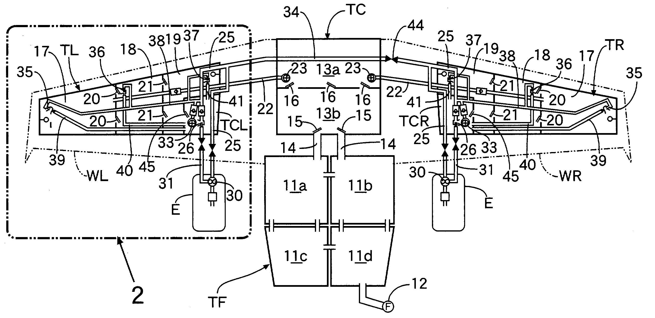
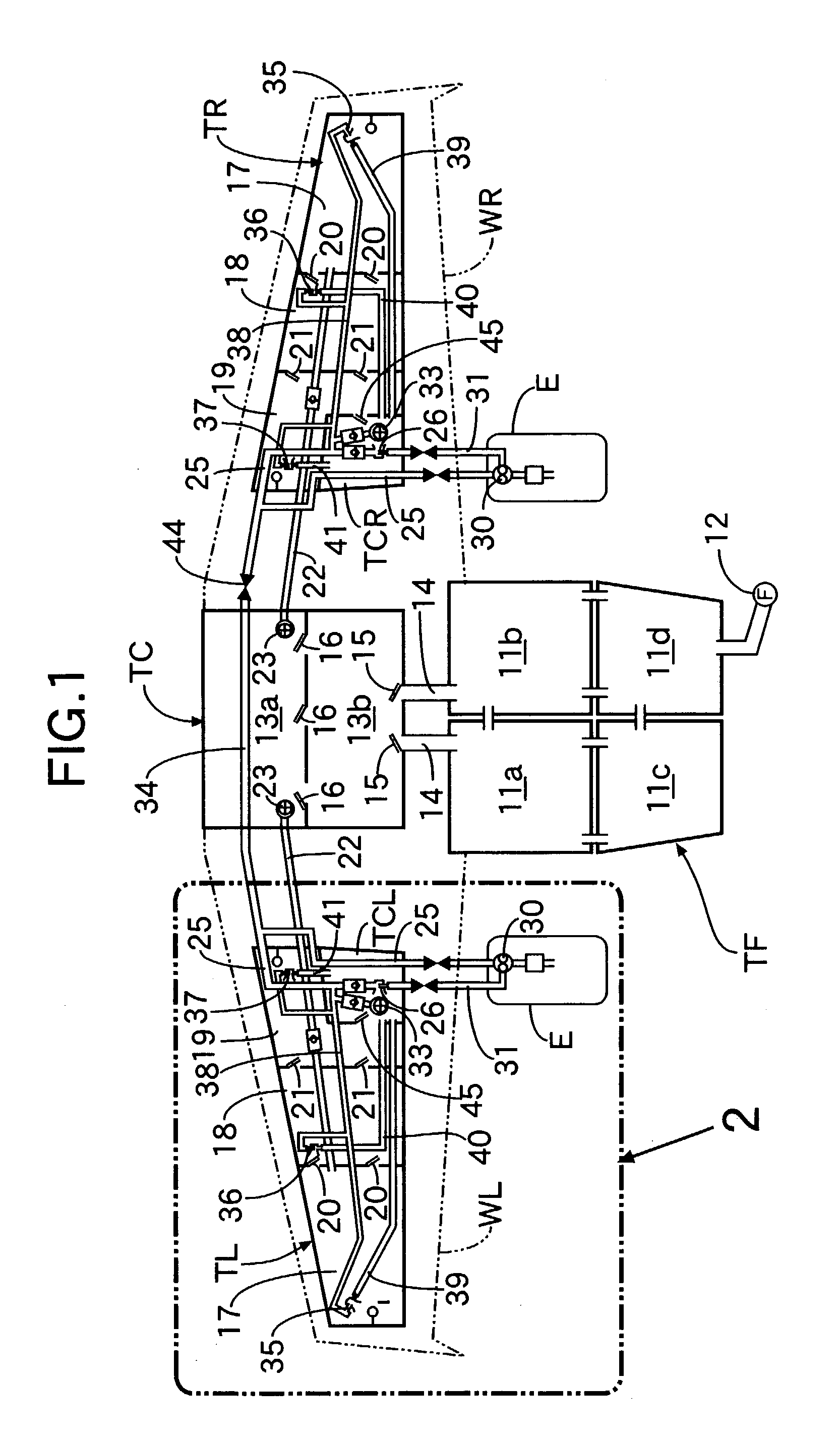
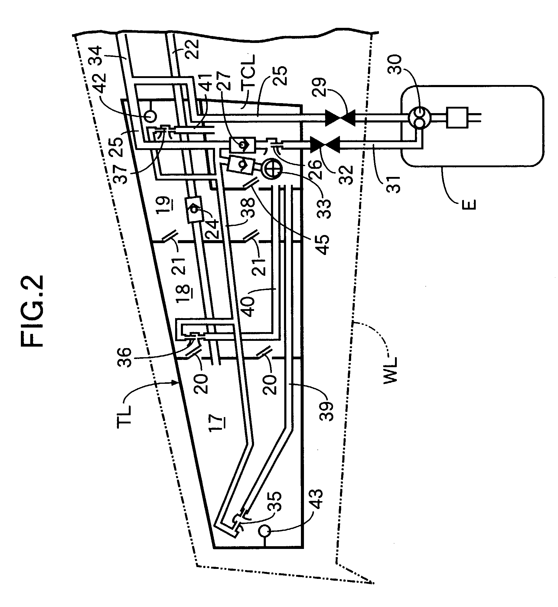
[0028] As shown in FIGS. 1 and 2, fuel supply systems for supplying fuel to engines E mounted in left and right main wings WL, WR of an airplane, include a fuselage fuel tank TF provided in a fuselage, a central wing fuel tank TC provided between the left and right main wings WL, WR, a left wing fuel tank TL provided in the left main wing WL, a right wing fuel tank TR provided in the right main wing WR, a left collector tank TCL provided in the left main wing WL, and a right collector tank TCR provided in the right main wing WR. The fuselage fuel tank TF has four sections 11a, 11b, 11c, 11d that communicate with each other, and a fuel inlet 12 is connected to one thereof, that is, the section 11d. The central wing fuel tank TC has two sections 13a, 13b; the section 13b on the rear side is connected to each of the sections 11a, 11b on the front side of the fuselage fuel tank TF via ...


PUM


Abstract

An airplane fuel supply system includes a wing fuel tank that is formed from a wing tip fuel tank having a wing tip fuel pump; a central fuel tank having a central fuel pump; and a wing root fuel tank having a wing root fuel pump. Fuel movement from the wing tip fuel tank to the central fuel tank is allowed by a flapper valve, and fuel movement from the central fuel tank to the wing root fuel tank is allowed by another flapper valve. When the fuel delivery volume of the wing tip fuel pump is represented by Vt, the fuel delivery volume of the central fuel pump is represented by Vc, the fuel delivery volume of the wing root fuel pump is represented by Vr, and the fuel delivery volume from a collector tank to the engine is represented by Ve, the fuel delivery volumes Vt, Vc, Vr, and Ve are set so as to satisfy the relationships Vr>Ve, Vt+Vc>Ve, and Vc<Ve. This can minimize the size of the fuel pumps for supplying fuel from the airplane wing fuel tank to the engine.

Description

[0001] 1. Field of the Invention[0002] The present invention relates to an airplane fuel supply system that supplies fuel within a wing fuel tank to an engine via a collector tank, the wing fuel tank including a wing tip fuel tank, a central fuel tank, and a wing root fuel tank. Furthermore, the present invention relates to a method for assembling a wing pipeline that extends in the span direction and runs through a partition provided within an airplane main wing.[0003] 2. Description of the Related Art[0004] A wing fuel tank provided in an airplane main wing has a plurality of sections that are divided in the span direction and communicate with each other. A fuel pump for supplying fuel to an engine is provided in each of the sections. When the airplane banks laterally in a state in which there is little fuel remaining in the wing fuel tank, fuel moves between the plurality of sections of the wing fuel tank, leading to a possibility that the fuel pump in an empty section does not f...

Claims


Application Information

Patent Timeline
IPC IPC(8): B64D37/08B64D37/20B64D37/28
CPCB64D37/08Y02T50/44B64D37/28B64D37/20Y02T50/40Y10T137/86196
Inventor GOTO, KENICHIFUJII, TOSHIAKI
Owner AMERICAN HONDA MOTOR COMPANY
Why Eureka
Try Eureka