Rack mountable computer component power distribution unit and method

a computer component and power distribution unit technology, applied in the direction of insulated conductors, cable connections, coupling devices, etc., can solve the problems of waste of space between the back plane space and the fan exhaust plenum, high cost of individual fans mounted in each component, and time-consuming replacement, etc., to facilitate the rearward re-direction of air flow

Inactive Publication Date: 2003-12-04
BOXX TECH LLC
View PDF39 Cites 12 Cited by
  • Summary
  • Abstract
  • Description
  • Claims
  • Application Information

AI Technical Summary

Benefits of technology

0071] FIGS. 21 through 24 illustrate further embodiments of the present invention. As illustrated in FIGS. 21 through 24, the intake and exhaust of the air flow may be varied to accommodate various configurations as to the availability of air supply in the immediate environment. For example, in FIG. 22, an air intake fan module 38a draws air from a bottom opening 25a, similar to that illustrated in the embodiment shown in FIGS. 1 through 21. Air flow is directed vertically with the aid of fans 43a mounted on fan / LAN trays. However, unlike the previously described embodiment, in the embodiment illustrated in FIG. 22, the air flow is re-directed from a vertical path of travel at right angles to a horizontal path of travel out of the rack system 10a towards the rear of the rack housing. An air flow hood 85a facilitates the rearward re-direction of the air flow.

Problems solved by technology

The individual fans mounted in each component are expensive, and time-consuming to replace in case of malfunctions.
Also, the back plane space and fan exhaust plenum chamber are wasted space in that they occupy spaces which could otherwise be filled with computer components.
Such an operation is time consuming, and therefore expensive since highly trained personnel are required to do such an installation.
This, too, is time consuming and expensive.
However, due to the cabling requirements for such a large number of computer components mounted in a single rack, it is difficult to install the components within the rack due to the cabling requirements and still have a very densely packed configuration.

Method used


Image

  • Rack mountable computer component power distribution unit and method
  • Rack mountable computer component power distribution unit and method
  • Rack mountable computer component power distribution unit and method

Examples


Embodiment Construction

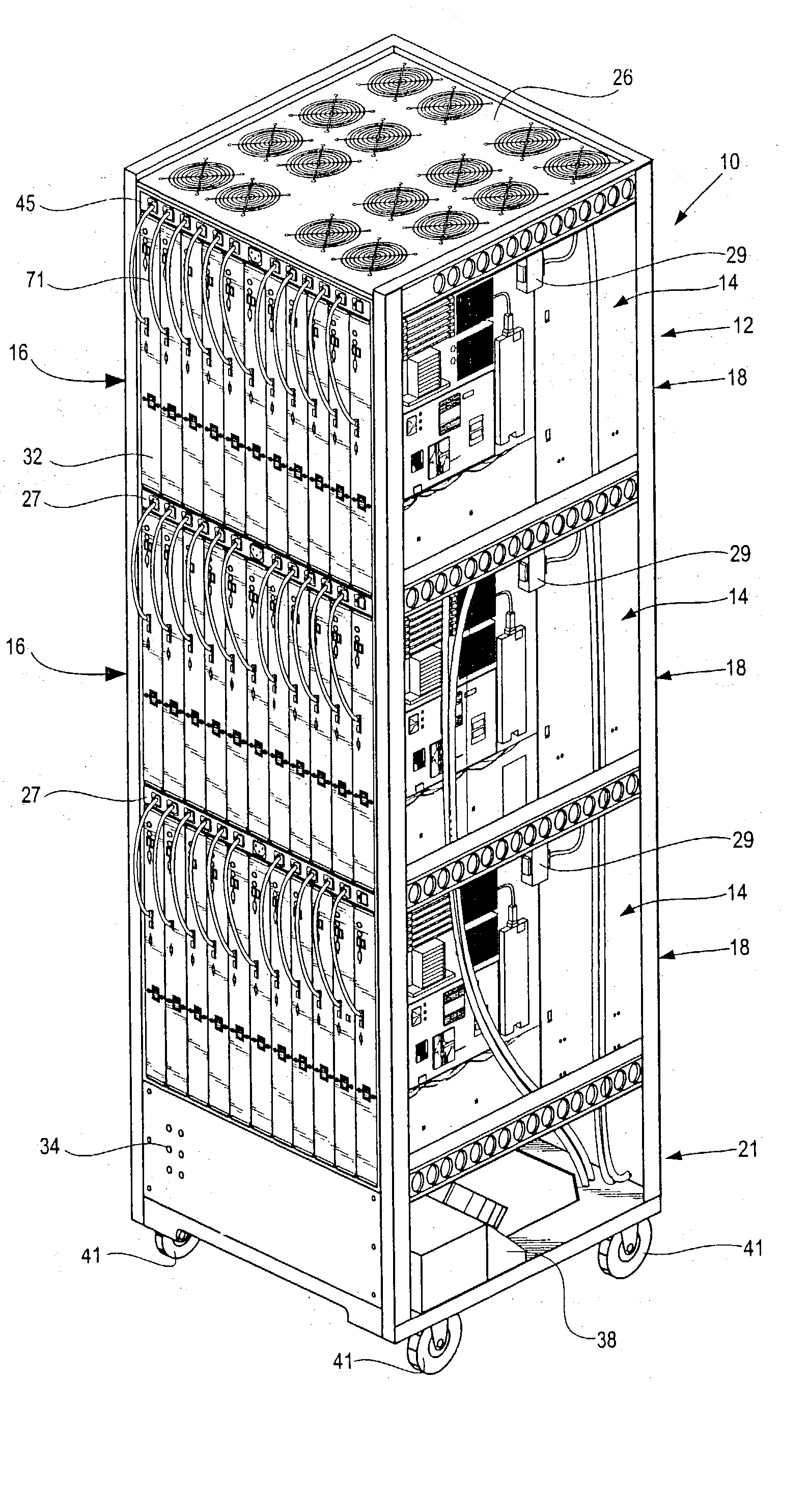
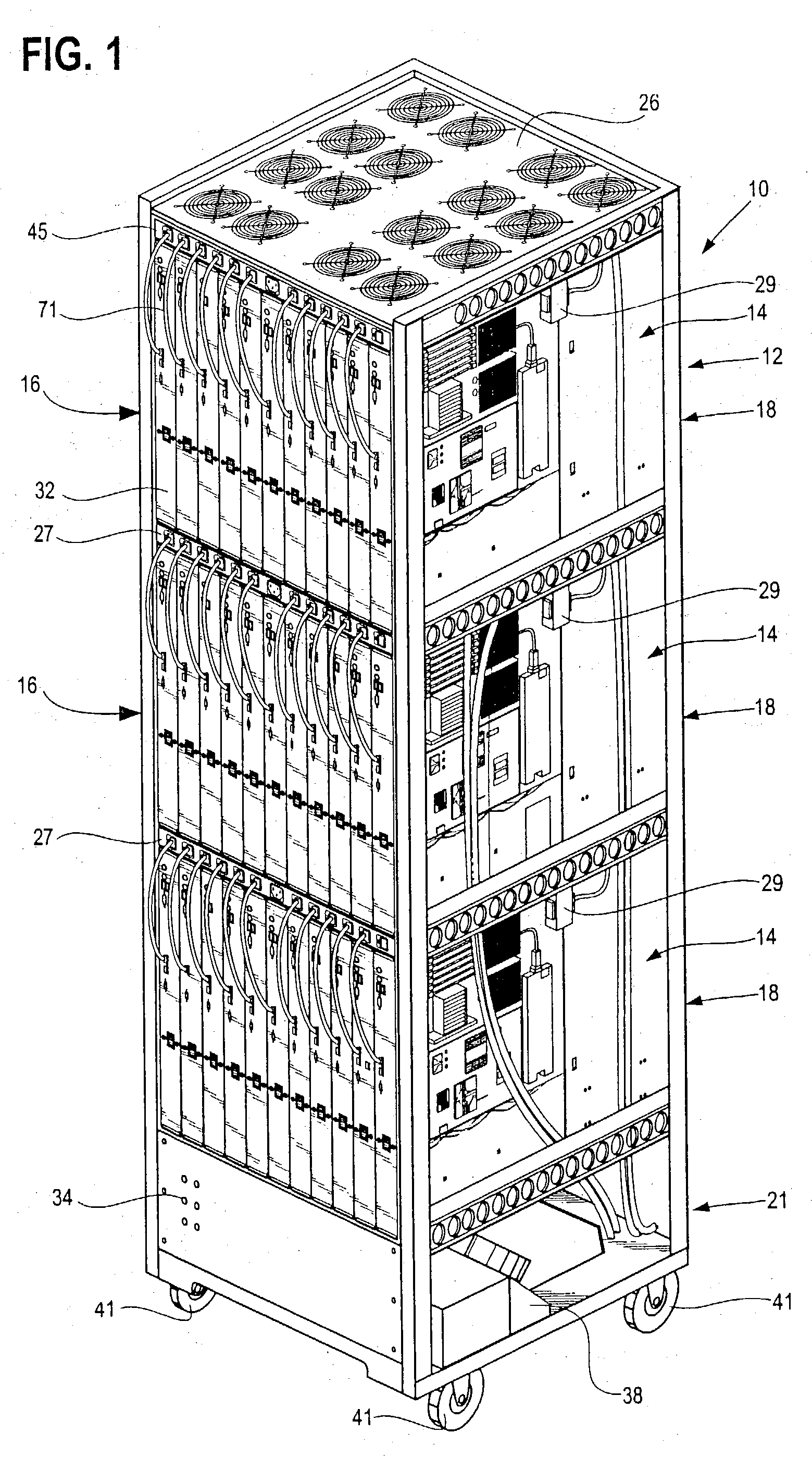
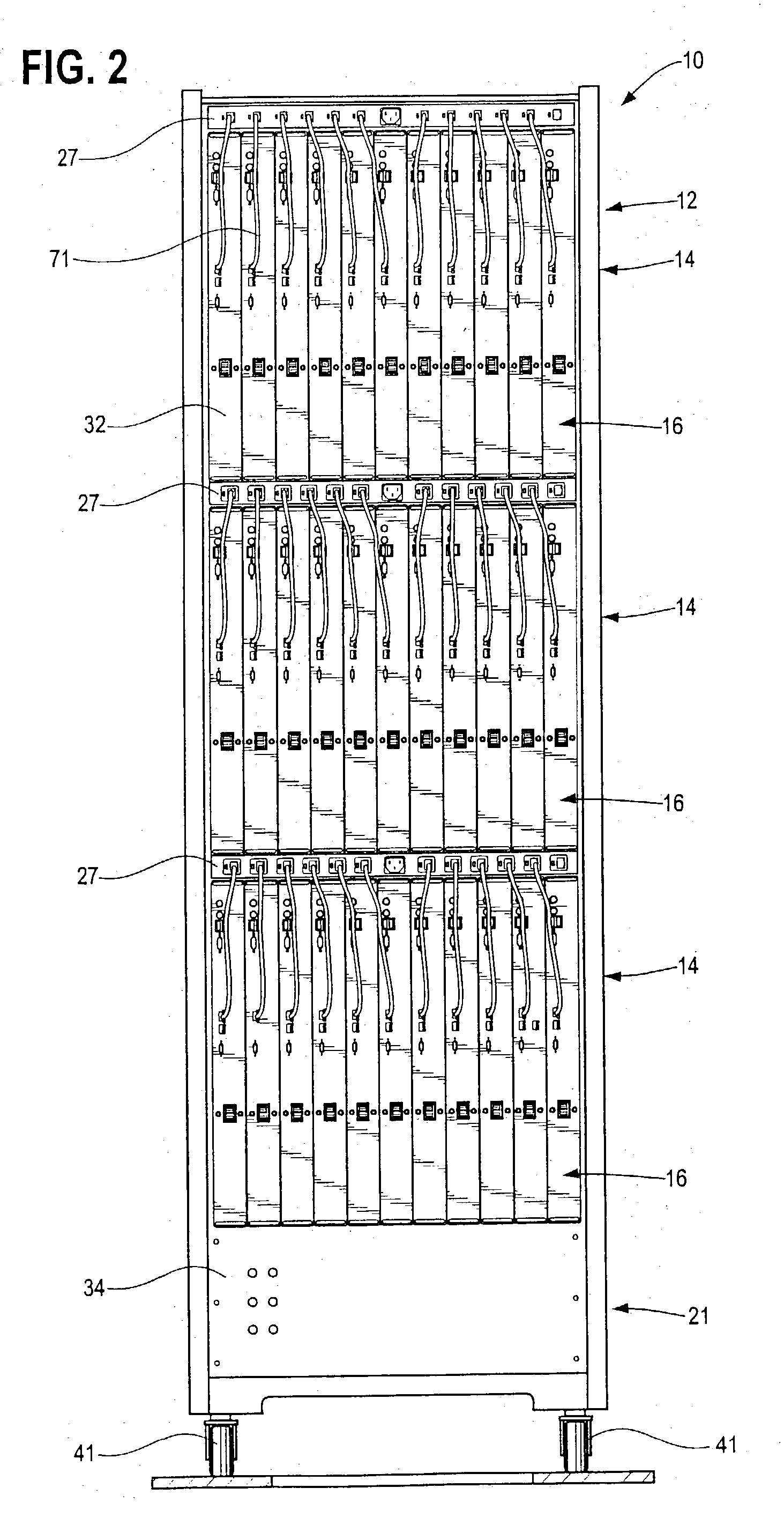
[0043] According to the disclosed embodiments of the invention, there is provided a method of supplying electrical power to a series of upright computer blades mounted side-by-side in a closely spaced configuration, including extending an elongated power distribution unit transversely to the upright blades, and electrically interconnecting the upright blades with a series of electrical connectors arranged side-by-side on one side of the distribution unit. In one embodiment of the invention, a second series of electrical connectors are arranged side-by-side on the opposite side of the body of the power distribution unit.

[0044] According to other embodiments of the invention, each one of the computer component blades has a similar cut out portion, and the body of the power distribution unit has a complementary cross sectional shape received by the cut-away portions of the blades to provide a compact mounting arrangement.

[0045] According to at least one of the disclosed embodiments of ...


PUM


Abstract

According to the disclosed embodiments of the invention, there is provided a method of supplying electrical power to a series of upright computer blades mounted side-by-side in a closely spaced configuration, including extending an elongated power distribution unit transversely to the upright blades, and electrically interconnecting the upright blades with a series of electrical connectors arranged side-by-side on one side of the distribution unit. In one embodiment of the invention, a second series of electrical connectors are arranged side-by-side on the opposite side of the body of the power distribution unit.

Description

[0001] This application claims priority to the following U.S. provisional applications: Serial No. 60 / 384,996, titled "Rack Mountable Computer Component and Method of Making Same", filed May 31, 2002; Serial No. 60 / 384,987, titled "Rack Mountable Computer Component Cooling Method and Device", filed May 31, 2002; Serial No. 60 / 384,986, titled "Rack Mountable Computer Component Fan Cooling Arrangement and Method", and Serial No. 60 / 385,005, titled "Rack Mountable Computer Component Power Distribution Unit and Method", which are each hereby incorporated by reference in their entirety.[0002] This application relates to the following U.S. non-provisional patent applications: Attorney Docket Number 7719-110, titled "Rack Mountable Computer Component and Method of Making Same," filed May 28, 2003; Attorney Docket Number 7719-111, titled "Rack Mountable Computer Component Cooling Method and Device," filed May 28, 2003; and Attorney Docket No. 7719-112, titled "Rack Mountable Computer Fan Co...

Claims


Application Information

Patent Timeline
Patent Type & Authority Applications(United States)
IPC IPC(8): G06F1/18G06F1/20H05K7/14H05K7/20
CPCG06F1/181G06F1/183H05K7/20736H05K7/1492G06F1/20
Inventor SMITH, JOHN V.HESTER, VICTOR P.WYLIE, WILLIAM A.
Owner BOXX TECH LLC
Why Eureka
Try Eureka