Unlock instant, AI-driven research and patent intelligence for your innovation.

Dual-band VHF-UHF antenna system

a dual-band, antenna technology, applied in the field of antenna systems, can solve the problems of increasing the requirements of installation that entail very heavy constraints

Inactive Publication Date: 2003-12-11
THALES SA
View PDF7 Cites 11 Cited by
  • Summary
  • Abstract
  • Description
  • Claims
  • Application Information

AI Technical Summary

Problems solved by technology

However, this solution gives rise to requirements of installation that entail very heavy constraints.

Method used


Image

  • Dual-band VHF-UHF antenna system
  • Dual-band VHF-UHF antenna system
  • Dual-band VHF-UHF antenna system

Examples


Embodiment Construction

[0031] In the different figures, the corresponding elements are designated by the same references.

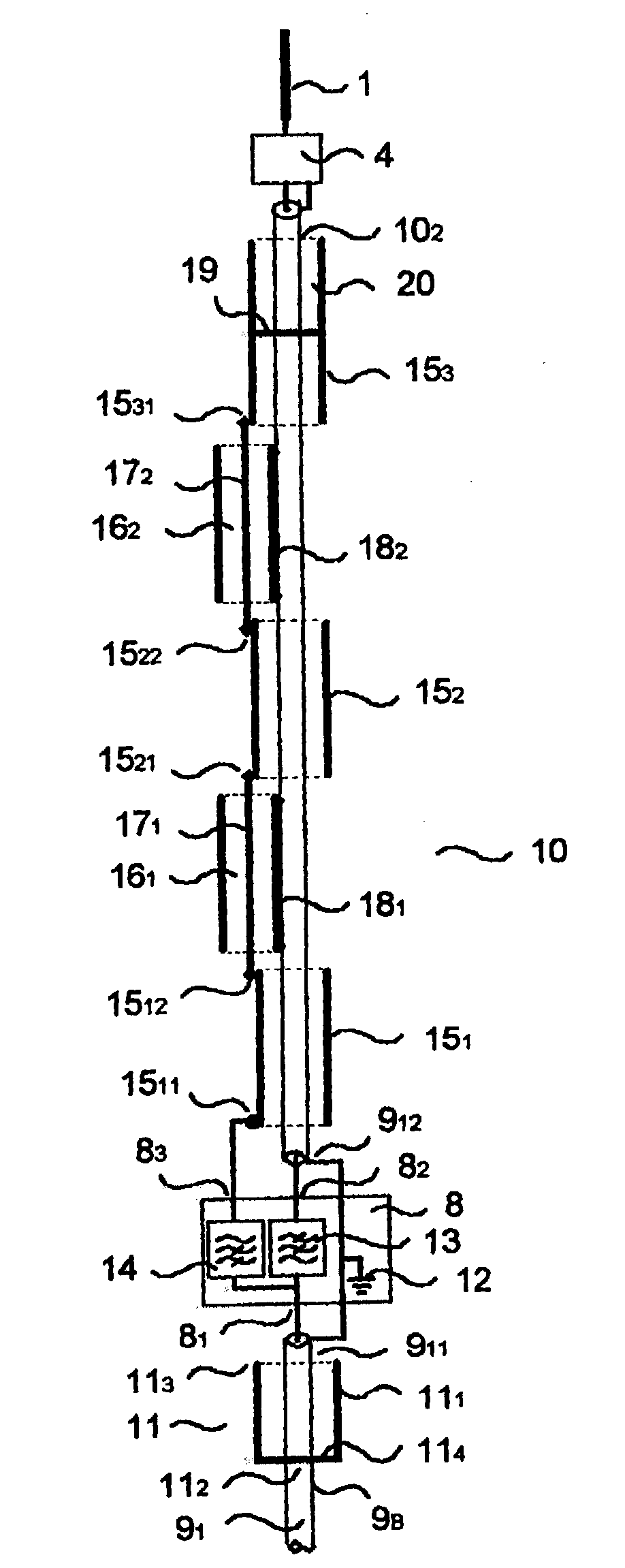
[0032] FIG. 3 shows a block diagram of an antenna according to the invention. This antenna is designed to work especially in the two frequency bands, namely the 30-88 MHz VHF band and the 2.4-2.5 GHz UHF band. In this example, the antenna is installed on a vehicle.

[0033] The antenna A is formed, for example, by a power supply device 4 connected to a transmitter-receiver station 7 through a transmission line 9 that is coaxial or substantially coaxial. The characteristic impedance value of this line is equal to the value usually adopted for radiocommunications systems, namely 50 ohms. The antenna comprises, for example:

[0034] an upper radiating element 1 made, for example, according to principles known to those skilled in the art, for example a conductive strand with a length of about 1.6 meters,

[0035] a lower radiating element 2 formed by a section 9.sub.1 of the coaxial transmission lin...


PUM


Abstract

A wideband antenna system is capable of radiating or receiving signals in a low-frequency band [Fbb, Fbh] covering more than one octave and a high-frequency band [Fhb, Fhh] with Fhb>=2Fbh comprising at least one power supply device (4) powering at least one upper radiating element (1) and at least one lower radiating element (2). The lower radiating element (2) is provided with at least one antenna assembly (10) adapted to radiating in the high-frequency band [Fhb, Fhh]. Application to RF signals.

Description

[0001] 1. Field of the Invention[0002] The present invention relates especially to an antenna system capable of working in several distinct frequency ranges, for example a first frequency band which is a low-frequency band [Fbb, Fbh] covering at least one octave and a second frequency band, which is a high frequency band [Fhb, Fhh], the two bands being separated by a difference such that Fhb>=2Fbh.[0003] 2. Description of the Prior Art[0004] Broadband antennas capable of working with radio equipment in the VHF (Very High Frequency) band, covering frequencies of 30 to 88 MHz, are known in the prior art.[0005] For example, the U.S. Pat. Nos. 4,496,953 and 4,302,760 describe antennas of this kind. FIG. 1 is an exemplary antenna A installed on a land vehicle V. The antenna is formed essentially by an upper radiating element 1 and a lower radiating element 2, both powered by means of a power supply device 4. A mounting base 5, usually provided with a spring 6 to protect the antenna fr...

Claims


Application Information

Patent Timeline
IPC IPC(8): H01Q5/00H01Q5/321H01Q9/16H01Q21/30
CPCH01Q9/16H01Q5/321H01Q21/30H01Q9/18
Inventor HUNG, FREDERIC NGO BUI
Owner THALES SA