Image data processing unit for use in a visual inspection device
a technology of image data and visual inspection device, which is applied in the direction of image enhancement, optical apparatus testing, instruments, etc., can solve the problems of large size of unevenness, difficult to detect unevenness, and uneven image data obtained by using a camera
- Summary
- Abstract
- Description
- Claims
- Application Information
AI Technical Summary
Benefits of technology
Problems solved by technology
Method used
Image

Examples
first embodiment
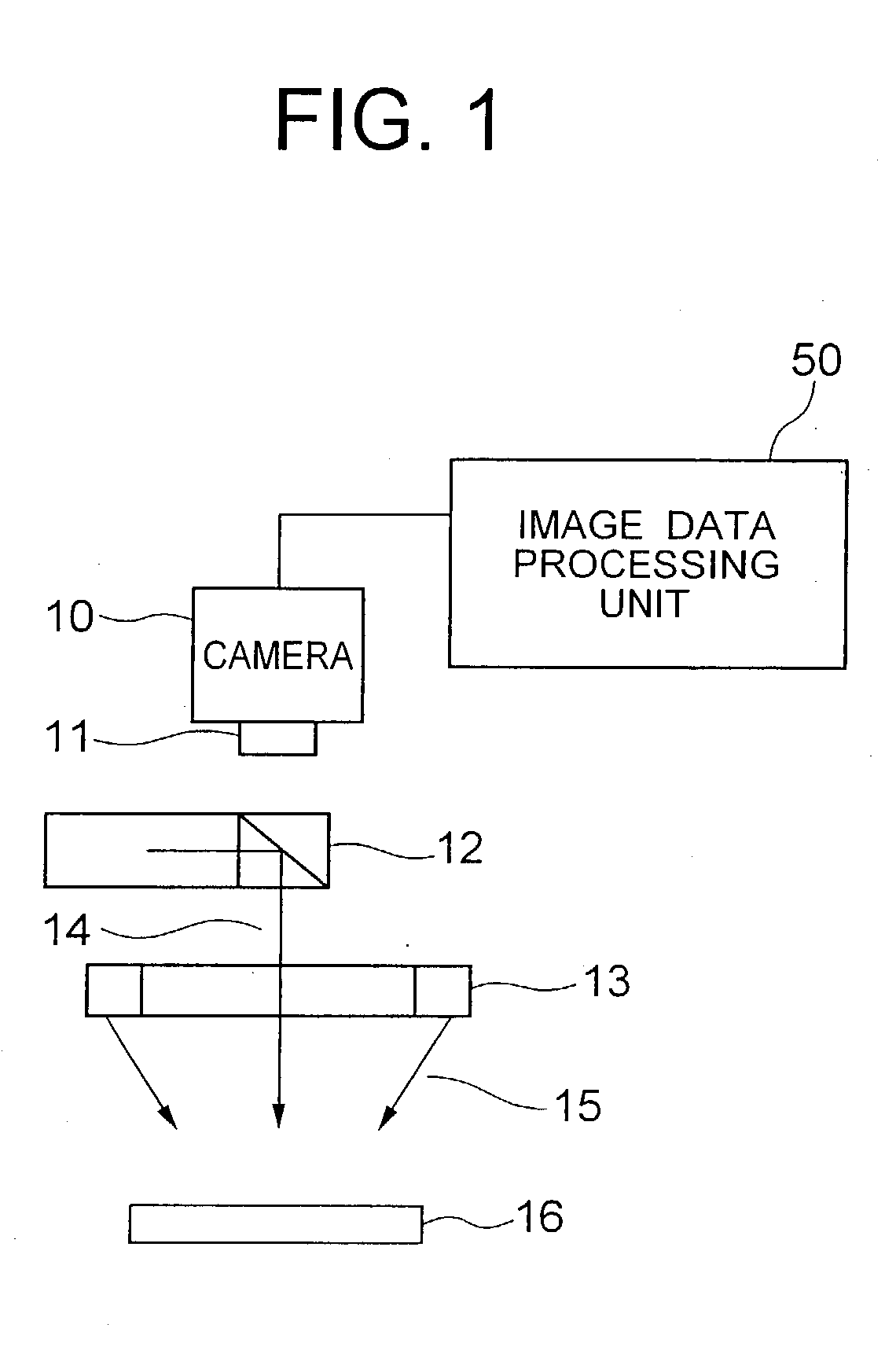
[0044] Referring to FIG. 1, a visual inspection device including an image data processing unit according to the present invention includes a camera 10 having an objective lens 11 for imaging an object pattern 16, a main lighting device 12, an auxiliary lighting device 13, and the image data processing unit 50 for processing the image signal obtained by the camera 10. The object pattern 16 is formed on the screen of a flat display panel such as a LCD unit or plasma display unit.
[0045] The main lighting device 12 emits co-axial light 14 co-axially irradiating the object pattern 16 from above, whereas the auxiliary lighting device 12 emits oblique light 15 obliquely irradiating the object pattern 16 from above. These lighting devices 12 and / or 13 may be omitted if the object pattern 16 is formed on the screen of a LCD unit or a monitor having a backlight unit.
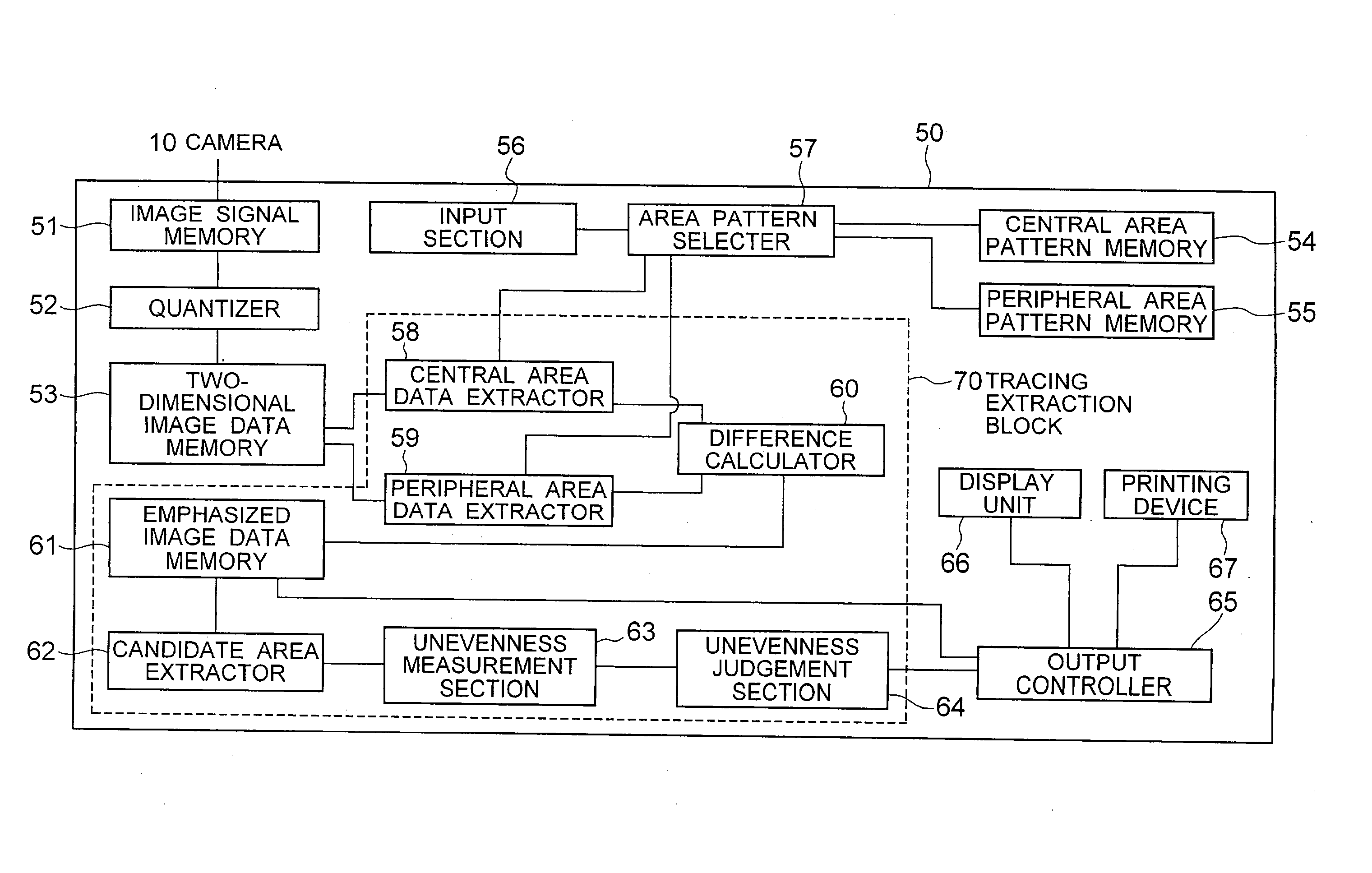
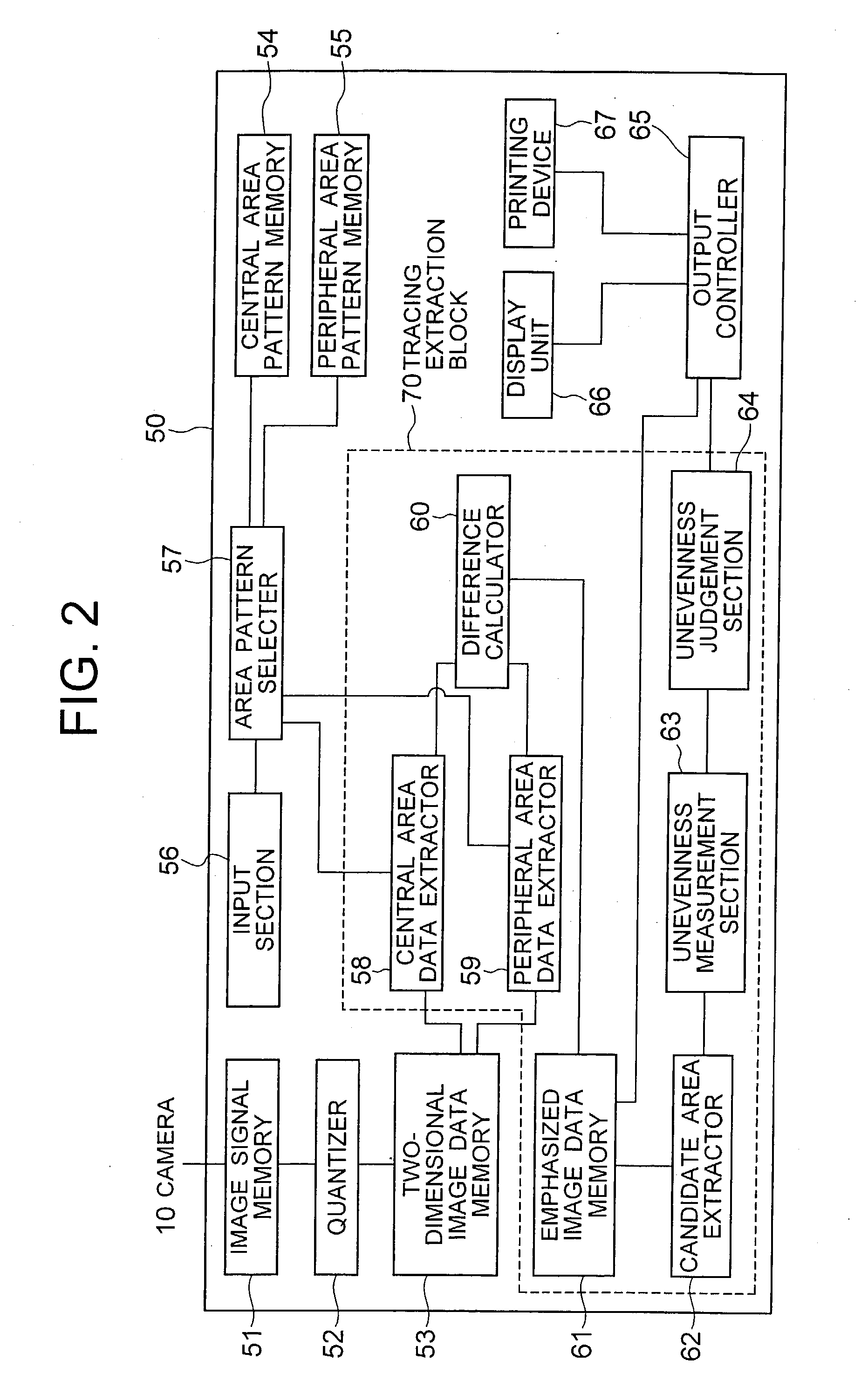
[0046] Referring to FIG. 2, the image data processing unit 50 includes image signal memory 51, quantizer 52, two-dimensional ima...
second embodiment
[0104] Referring to FIG. 20, an image data processing unit 50A according to the present invention is similar to the image data processing unit 50 of FIG. 2, except that the image data processing unit 50A of the present embodiment includes an area pattern composer 68 in addition to the configuration of the image data processing unit 50. The area pattern composer 68 composes the central area pattern and / or the peripheral area pattern based on the instruction input through the input section 56, delivering the composed area patterns to the area pattern selector 57. The central and peripheral area patterns composed by the area pattern composer 68 may be stored in the central and peripheral area pattern memories 54 and 55, respectively.
[0105] The area pattern composer 68 receives through the input section 56 information of the shape and size of the uneven area to be extracted, quantizes the uneven area of the information received and creates the central area pattern based on the quantized...
third embodiment
[0108] Referring to FIG. 23, the image data processing unit 50B according to the present invention is similar to the image data processing unit 50 except that the image data processing unit 50B has a plurality of tracing extraction blocks 70a, 70b and 70c. The area pattern selector 57 selects a plurality of central area patterns and a plurality of peripheral area patterns each corresponding to one of a plurality of desired uneven areas to be emphasized, whereby each of the tracing extraction blocks 70a, 70b and 70c prepares emphasized image data by using a combinational pattern including a corresponding central area pattern and a corresponding peripheral area pattern for judgement of a desired uneven area.
[0109] Referring to FIGS. 24A, 24B and 24C, when the area pattern selector 57 selects central area patterns 21H, 21I and 21J shown in FIGS. 24A, 24B and 24C having L.times.L, M.times.M and N.times.N pixel sizes, respectively, as well as peripheral area patterns 22H, 22I and 22J sho...
PUM
| Property | Measurement | Unit |
|---|---|---|
| pixel size | aaaaa | aaaaa |
| brightness | aaaaa | aaaaa |
| area | aaaaa | aaaaa |
Abstract
Description
Claims
Application Information