Fan arrangement for an electrical machine

a technology for electrical machines and fans, applied in machines/engines, stators, liquid fuel engines, etc., can solve problems such as noise generation, flow separation and turbulence, and impair the fan outpu

Inactive Publication Date: 2003-12-11
ROBERT BOSCH GMBH
View PDF8 Cites 0 Cited by
  • Summary
  • Abstract
  • Description
  • Claims
  • Application Information

AI Technical Summary

Problems solved by technology

It is disadvantageous that bearing plates of the prior art are embodied with sharp edges, which result in flow separations and turbulence.
Such a disrupted flow generates noise and impairs the fan output.
This impairs the fan output.
Another disadvantageous effect of the appar

Method used


Image

  • Fan arrangement for an electrical machine
  • Fan arrangement for an electrical machine
  • Fan arrangement for an electrical machine

Examples


Embodiment Construction

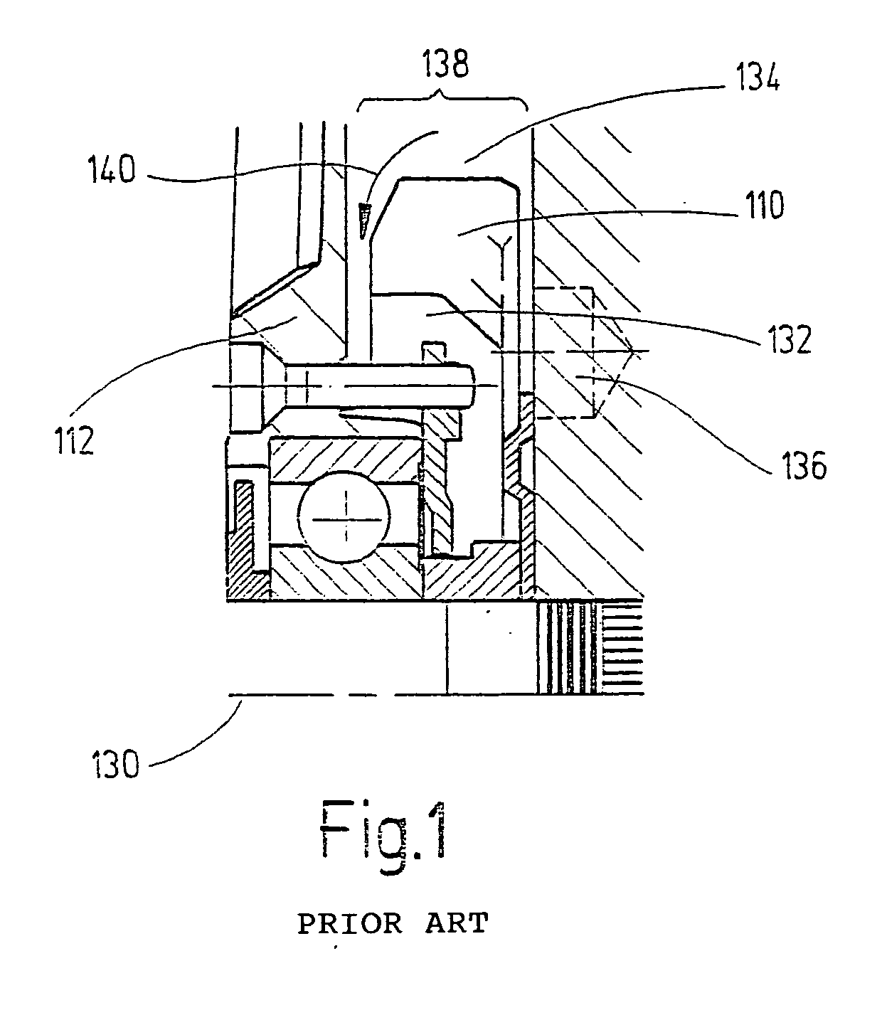
[0018] The depiction of the prior art according to FIG. 1 has already been explained in the general section of this specification.

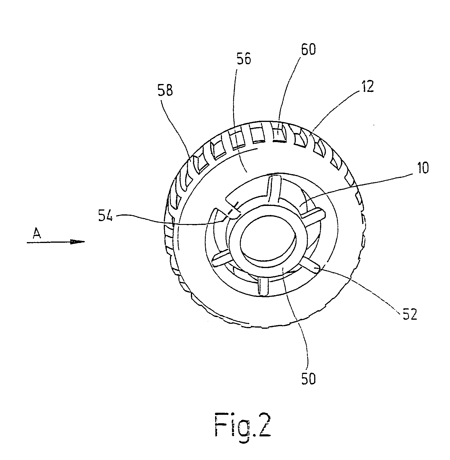
[0019] FIG. 2 shows a perspective depiction of a bearing plate 12 and the associated apparatus of a fan 10 according to the current invention. The bearing plate 12 has an essentially cylindrical region 50 close to the axis. A number of struts 52 extend from this cylindrical region 50. These struts 52 are wider on the side oriented toward the viewer and taper in the direction toward the fan 10. The cross section of the struts 52 is teardrop-shaped along an intersecting plane that is aligned axially and is indicated by the dashed line 54. A rounded region 56 of the bearing plate adjoins the struts 52. This rounded region 56 transitions into a region 58 that extends in the axial direction. The region 58 extending in the axial direction has a number of openings 60, which permit the heated air to escape.

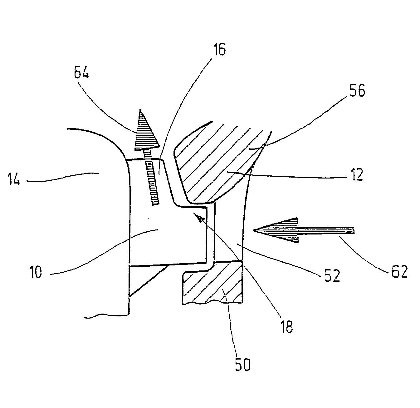
[0020] FIG. 3 shows a sectional view of a fan apparatus a...


PUM


Abstract

The invention relates to a fan apparatus for an electrical machine, with a fan (10), which can be rotated around an axis, wherein air flows into the fan (10) in the axial direction and out of the fan (10) in the radial direction, a bearing plate (12), and a magnet wheel (14), wherein a flow conduit (16) is at least partially bounded by the bearing plate (12) and the magnet wheel (14) and the flow cross section of the flow conduit (16) is essentially constant in the radial direction.

Description

[0001] The invention relates to a fan apparatus for an electrical machine, with a fan, which can rotate around an axis and causes air to flow into the fan axially and out of the fan radially, a bearing plate, and a magnet wheel, in which a flow conduit is at least partially bounded by the bearing plate and the magnet wheel.PRIOR ART[0002] Operation of electrical machines naturally involves the generation of heat. It is desirable to dissipate this heat. Fans are frequently used for this purpose; they are supported so that they can rotate around the axis of the electrical machine. Upon rotation of the fan, air flows axially into the fan and radially out of the fan.[0003] In generators that are used in motor vehicles, the housing is partially embodied as a bearing plate. Such a bearing plate extends radially outward from the bearing of a rotor shaft and then constitutes part of the axially extending outer surface of the generator. As a result, the bearing plate influences both the infl...

Claims


Application Information

Patent Timeline
IPC IPC(8): H02K5/16H02K5/20H02K9/06
CPCH02K5/16H02K9/06H02K5/20H02K5/207
Inventor BRAUN, HORSTBERGER, THOMASKNAPPENBERGER, UWE
Owner ROBERT BOSCH GMBH
Why Eureka
Try Eureka