Memory compression for computer systems

a computer system and memory technology, applied in the field of computer systems, can solve the problems of less storage capacity available, limited storage capacity of buffer cache, and very slow access to persistent storage devices

Inactive Publication Date: 2003-12-11
VALTRUS INNOVATIONS LTD +1
View PDF9 Cites 56 Cited by
  • Summary
  • Abstract
  • Description
  • Claims
  • Application Information

AI Technical Summary

Problems solved by technology

Since access to the persistent storage device is very slow, the OS reads data in large units, known as "data blocks", and stores them in the main memory.
The buffer cache has limited storage capacity compared to the large amounts of data that the computer programs can operate on for two main reasons.
First, the buffer cache is part of the main memory, which is more expensive and hence has less storage capacity available than the persistent storage device.
Second, the OS allocates only a part of the main memory to the buffer cache.
Since the buffer cache contains only a small amount of storage capacity compared to the amount of data in the persistent storage device that will be accessed by the program, the buffer cache often runs out of storage space.
These data blocks cannot be used for reading data from the persistent storage device until the changed data is written out first.
This will delay the execution of the program further.
In most cases, however, the program will be delayed because it needs to wait for the data it requires to be read from the persistent storage device.
However, this may not be possible for computer systems dedicated to one main task, such as computationally demanding computer simulations.
However, such prediction is not always successful.
Thus, programs run on computer systems have performance problems when accessing large amount of data stored on persistent storage devices because the access to persistent storage devices are much slower than primary storage devices such as the main memory.
It is not always desirable to add extra memory due to factors such as cost or limitations imposed by the physical system design.
The lack of adequate main memory can severely degrade the performance of these programs.
However, such solution is both costly and time-consuming.
However, accessing these persistent storage devices is still quite slow.

Method used


Image

  • Memory compression for computer systems
  • Memory compression for computer systems
  • Memory compression for computer systems

Examples


Embodiment Construction

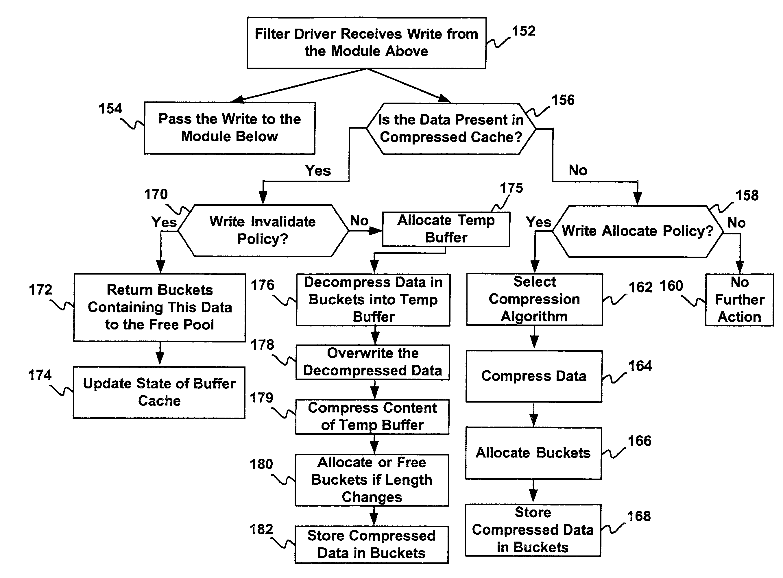
[0023] The present invention uses a unique method to hide latency involved in accessing a persistent storage device such as a hard disk. In an embodiment of the present invention, a part of the main memory is allocated as a first buffer cache and a second buffer cache. The first buffer cache is regular cache and the second buffer cache is a "compressed cache" where data blocks are stored after compression. A software module ("filter driver") is introduced wherein the filter driver is invoked every time the operating system (OS) reads or writes from the persistent storage device. The invocation is possible since the filter driver can be plugged into the OS with an OS compatible interface. No modification to the OS is required according to an embodiment of the present invention.

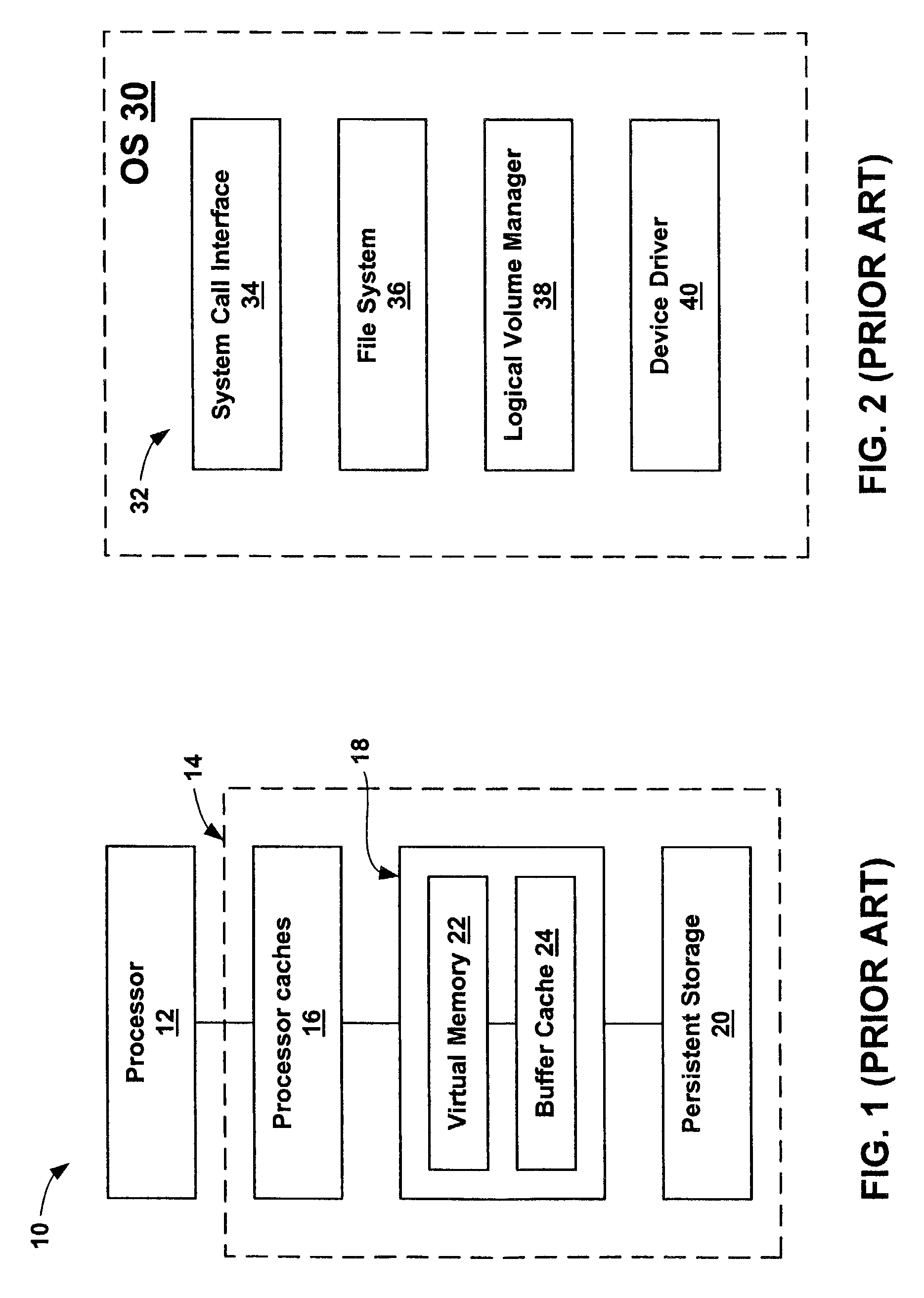
[0024] Referring now to FIG. 1 (PRIOR ART), therein is shown a prior art computer system 10. The computer system 10 includes a processor 12 and a memory system 14 connected to the processor 12. The memory syste...


PUM


Abstract

A computer system is provided including a processor, a persistent storage device, and a main memory connected to the processor and the persistent storage device. The main memory includes a compressed cache for storing data retrieved from the persistent storage device after compression and an operating system. The operating system includes a plurality of interconnected software modules for accessing the persistent storage device and a filter driver interconnected between two of the plurality of software modules for managing memory capacity of the compressed cache and the buffer cache.

Description

[0001] 1. Technical Field[0002] The present invention relates generally to computer systems and more particularly to memory compression in computer systems.[0003] 2. Background Art[0004] A computer system typically includes a processor and volatile memory, which stores data for computer programs (programs) being executed by the computer system. The volatile memory includes a main memory typically using dynamic random-access memory (DRAM) technology. The volatile memory might additionally include caches, typically using static random-access memory (SRAM) technology. The computer system also includes one or more persistent storage devices, such as hard disks, optical storage disks, magnetic tape drives, etc., which have high memory storage capacities.[0005] In operation, a computer program reads and / or writes data stored in the persistent storage devices using an Operating System (OS) running on the computer system. The OS invokes appropriate software modules to identify the locations...

Claims


Application Information

Patent Timeline
Patent Type & Authority Applications(United States)
IPC IPC(8): G06F12/08
CPCG06F12/0866Y10S707/99942G06F2212/401G06F2212/311
Inventor BASU, SUJOYROY, SUMITKUMAR, RAJENDRA
Owner VALTRUS INNOVATIONS LTD
Why Eureka
Try Eureka