Electronic device for controlling a synchronous motor with permanent-magnet rotor

a technology of magnetic rotor and synchronous motor, which is applied in the direction of electronic commutators, single motor speed/torque control, synchronous motor starters, etc., can solve the problems of unfavorable motor start, unfavorable motor start, and overheating of the motor

Inactive Publication Date: 2003-12-18
FAGOR
View PDF7 Cites 31 Cited by
  • Summary
  • Abstract
  • Description
  • Claims
  • Application Information

AI Technical Summary

Problems solved by technology

This causes unnecessary overheating of the motor, undesired vibrations and noise.
On the other hand, starting is a problem with this type of motor.
The device

Method used


Image

  • Electronic device for controlling a synchronous motor with permanent-magnet rotor
  • Electronic device for controlling a synchronous motor with permanent-magnet rotor
  • Electronic device for controlling a synchronous motor with permanent-magnet rotor

Examples


first embodiment

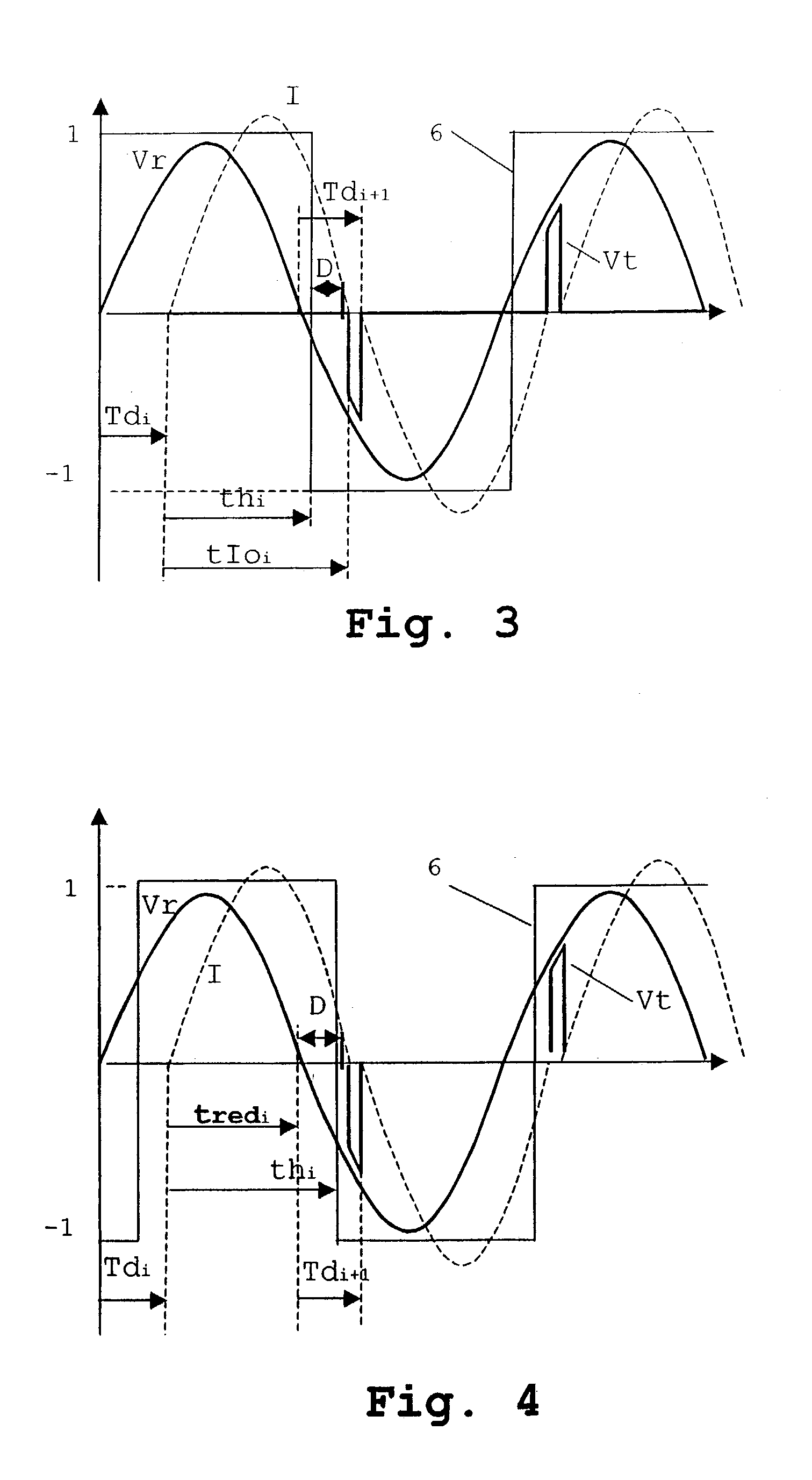
[0018] FIG. 3 shows the variations in time of the mains voltage, the signal from the rotor position sensor and the voltage in the switch in the invention.

second embodiment

[0019] FIG. 4 shows the variations in time of the mains voltage, the signal from the rotor position sensor and the voltage in the switch in the invention.

DETAILED DISCLOSURE OF THE INVENTION

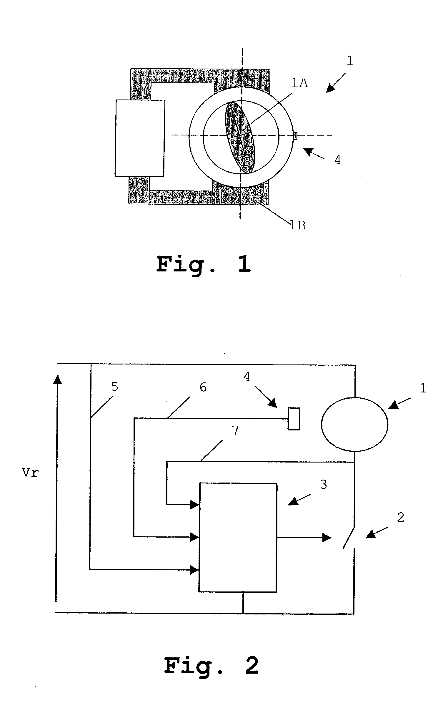
[0020] With reference to FIG. 1, the electronic device of the invention is applied to a permanent-magnet synchronous motor 1 with a rotor 1A and a stator 1B. Said motor 1 has two rotor poles and two stator poles, and is shown purely by way of an example.

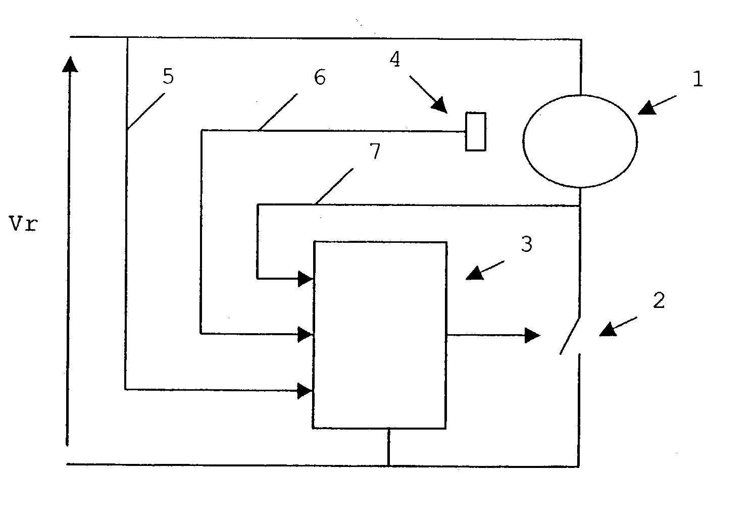
[0021] With reference to FIG. 2, the electronic device for controlling said synchronous motor 1 comprises:

[0022] an alternating voltage source at mains frequency providing a voltage Vr, connected in series with said synchronous motor 1,

[0023] a static switch 2 connected in series with said synchronous motor 1 and comprising for example a triac, and

[0024] an electronic circuit 3 which acts on said static switch 2.

[0025] Said electronic circuit 3 determines the timing for firing the static switch taking as reference the zero-crossing of the mains vo...


PUM


Abstract

Electronic device for controlling a synchronous motor with permanent-magnet rotor, comprising an alternating voltage current source at mains frequency connected in series with said synchronous motor (1), at least one static switch (2) connected in series with said synchronous motor (1), and an electronic circuit (3) that acts on said static switch (2). Said electronic circuit (3) determines the timing for the firing of the static switch (2) taking as reference the zero-crossing of the mains voltage (Vr) and applying a firing time (Td) starting from said reference, said firing time (Td) being obtained as a function of the position of the rotor (1A) of the motor (1) in the previous half-cycles.

Description

[0001] The present invention relates to the control of synchronous motors with a permanent-magnet rotor.PRIOR ART[0002] Synchronous motors with permanent-magnet rotors fed from the mains voltage are known. Applying said voltage to the motor generates a magnetic field between the poles of the stator of said motor, which turns the rotor of the motor over.[0003] For example, in the case of a motor with two stator poles and two rotor poles, when the rotor reaches synchronisation speed, i.e. in a permanent regime, the angular positions of the rotor, from 0.degree. to 180.degree. (a half turn) coincide with a given polarity of the current (current half-cycle), and the angle positions from 180.degree. to 360.degree. (the remaining half turn) coincide with the other current polarity (the following half-cycle of the current). In practice, phase shifts occur between the position of the rotor and the current signal, so that part of the current, rather than helping to drive the rotor, produces ...

Claims


Application Information

Patent Timeline
IPC IPC(8): H02P6/08H02P6/14
CPCH02P1/465H02P6/14H02P6/08H02P6/00H02P6/22
Inventor DE NANCLARES, EDUARDO BELTRANMITXELENA ALZURI, JOSE M.
Owner FAGOR
Why Eureka
Try Eureka