System for storing and recoving energy and method for use thereof

a technology applied in the field of energy storage and recovery system, can solve the problems of reducing the efficiency of electricity generation, and reducing the efficiency of electricity generation, and achieve the effect of reducing the pressure of hydrogen gas

Inactive Publication Date: 2004-01-22
PROTON ENERGY SYST
View PDF12 Cites 111 Cited by
  • Summary
  • Abstract
  • Description
  • Claims
  • Application Information

AI Technical Summary

Benefits of technology

0009] An embodiment for operating an energy storage and recovery system includes generating and conditioning electrical power from a renewable power source, powering an electrochemical cell system with the conditioned electrical power and water to electrolytically produce hydrogen gas, drying the hydrogen gas in a dryer to remove water, storing the hydrogen gas at a first pressure, and supplying the hydrogen gas at a second pressure to a hydrogen fueled electricity generator to produce electrical power in response to the electrical power generated by the renewable power source being less than or equal to a selected level. The hydrogen gas supplied to the hydrogen fueled electricity generator flows through the dryer and absorbs water prior to flowing into the hydrogen fueled electricity generator. The second pressure is less than the first pressure.
0010] An embodiment for operating a regenerative electrochemical cell system includes introducing water and power to an electrolysis module to produce hydrogen and oxygen, directing the hydrogen through a phase separation device and a dryer, thereby producing dry hydrogen, to a hydrogen storage device at a pressure, hydrating the dry hydrogen by reducing the pressure of the dry hydrogen from the hydrogen storage device and, passing the dry hydrogen through the dryer thereby transferring water from the dryer to

Problems solved by technology

Geographically remote areas such as islands or mountainous regions are often not connected to main utility electrical grids due to the cost of installing and maintaining the necessary transmission lines to carry the electricity.
Even in remote communities where the transmission lines are in place, it is not uncommon for frequent and extended power outages due to weather related faults.
In either case, to prevent economic loss in times of an electrical outage, it is often necessary for these communities or industries in these regions to create local "micro" electrical grids to ensure a reliable and uninterruptible power system.
This uninterruptible power sy

Method used


Image

  • System for storing and recoving energy and method for use thereof
  • System for storing and recoving energy and method for use thereof
  • System for storing and recoving energy and method for use thereof

Examples


Embodiment Construction

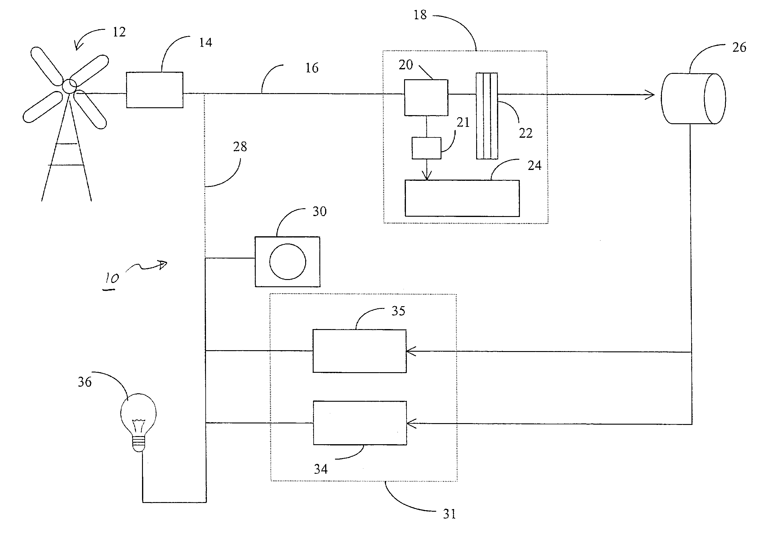
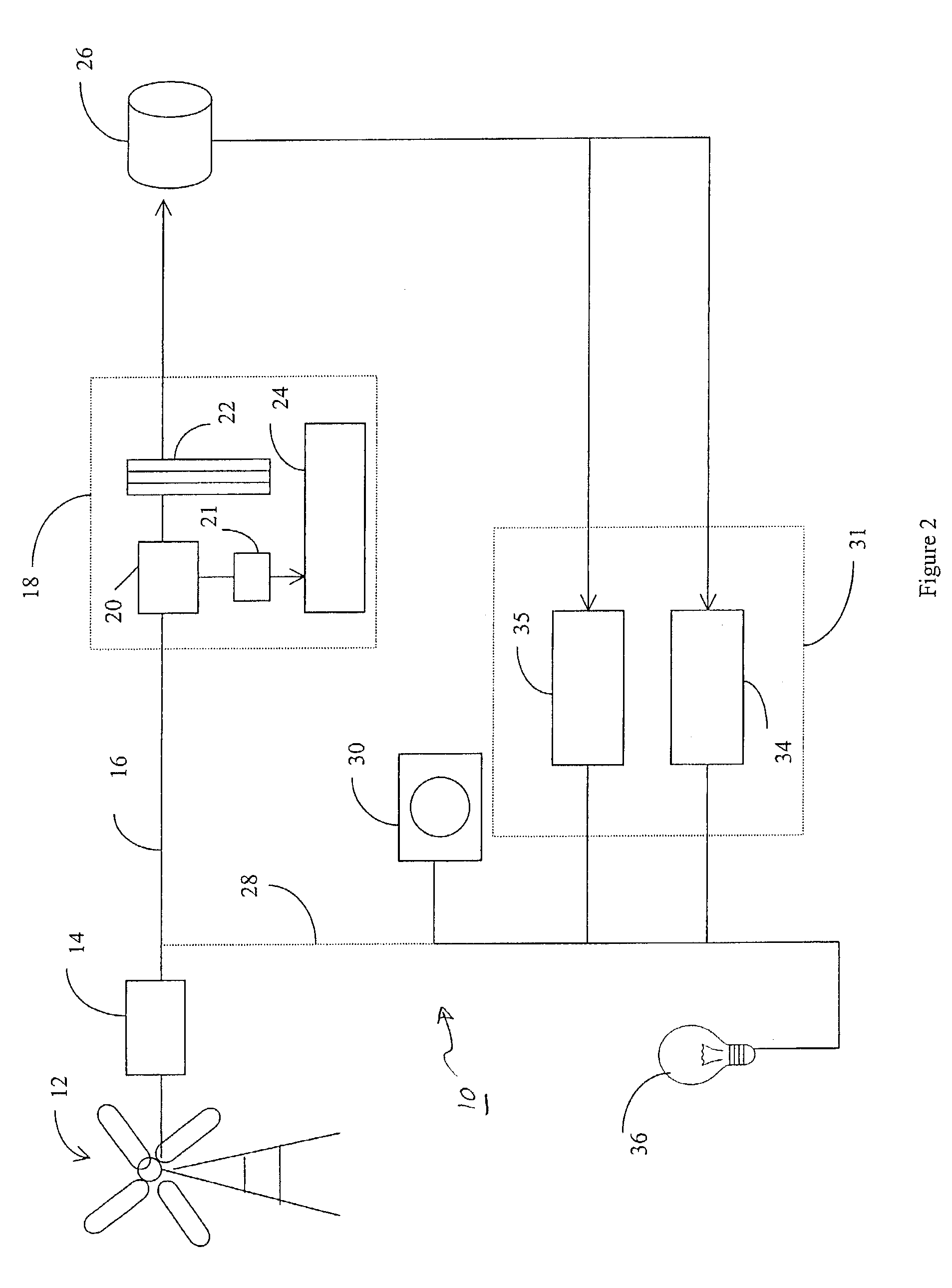
[0019] Generally, the device disclosed herein, in one embodiment, can comprise a renewable power source 12, a hydrogen generation device 22, a hydrogen storage device 26 and a hydrogen fueled electricity generator 31.

[0020] Another embodiment of the energy storage and recovery system comprises a hydrogen generator 18 in fluid communication with a storage device 26 that is in fluid communication with a hydrogen fueled electricity generator 31 such as a fuel cell 34 or internal combustion generator set 35 (i.e., genset). The internal combustion genset 35 comprises a hydrogen fueled internal combustion engine coupled with a generator.

[0021] Another embodiment of the energy storage and recovery system comprises a renewable power source 12, a regenerative electrochemical cell system 39 (also referred herein as the regen-system, and the regenerative energy system) having a power conditioner 40, an electrolysis module 41, and a fuel cell module 42. The regenerative electrochemical device 3...


PUM


Abstract

An energy storage and recovery system includes a renewable power source, a hydrogen generation device in electrical communication with the renewable power source, a hydrogen storage device in fluid communication with the hydrogen generation device, a hydrogen fueled electricity generator in fluid communication with the hydrogen storage device, and a pressure regulator interposed between and in fluid communication with the hydrogen fueled electricity generator and the hydrogen storage device. The pressure regulator is set at an operating pressure of the hydrogen fueled electricity generator.

Description

[0001] This application claims the benefit of U.S. Provisional Application Ser. No. 60 / 358,478, filed Feb. 19, 2002, which is incorporated by reference in its entirety.[0002] This disclosure relates generally to electrochemical cell systems, and especially relates to the storage and recovery of energy from a renewable power source.[0003] Geographically remote areas such as islands or mountainous regions are often not connected to main utility electrical grids due to the cost of installing and maintaining the necessary transmission lines to carry the electricity. Even in remote communities where the transmission lines are in place, it is not uncommon for frequent and extended power outages due to weather related faults. In either case, to prevent economic loss in times of an electrical outage, it is often necessary for these communities or industries in these regions to create local "micro" electrical grids to ensure a reliable and uninterruptible power system. This uninterruptible p...

Claims


Application Information

Patent Timeline
IPC IPC(8): H01M8/00H01M8/04H01M8/06H01M8/10
CPCH01M8/04089Y02E60/366H01M8/04156H01M8/04201H01M8/04253H01M8/04261H01M8/0656H01M2250/10H01M2250/20H01M2250/402Y02B90/12C25B15/08C25B1/04Y02E60/50Y02B90/14Y02T90/32Y02E70/10Y02E70/20H01M8/04126H01M16/003H01M8/04197Y02B90/10Y02E60/36Y02T90/40Y02P20/133
Inventor MOLTER, TRENTMOULTHROP, LARRYSPERANZA, JOHNSMITH, WILLIAM
Owner PROTON ENERGY SYST
Why Eureka
Try Eureka