Antenna system

a technology of anantenna and a beam beam is applied in the field of anantenna systems, which can solve the problems of increasing the interference level of the network, reducing the overall traffic capacity, and the strongest received signal direction is the best transmit direction for frequency division duplex systems, etc., and achieves the effect of reducing boresight power and increasing beam width

Inactive Publication Date: 2004-01-22
NOKIA SOLUTIONS & NETWORKS OY
View PDF6 Cites 10 Cited by
  • Summary
  • Abstract
  • Description
  • Claims
  • Application Information

AI Technical Summary

Benefits of technology

0025] FIG. 8 illustrates the increase in beamwidth as the boresight power is reduced, in embodiments of the present invention.

Problems solved by technology

The assumption that the strongest received signal direction is the best transmit direction may not be correct for frequency division duplex systems (such as for Global System for Mobile communications (GSM) systems).
This increases the interference level in the network, so reducing overall traffic capacity and increasing power consumption within the base station.
This makes the mobile stations in close proximity to the base station very difficult to locate because the direction from which the strongest signal is received may be very different to the direction from which the signal was originally transmitted.
This is disadvantageous because the increased beam width away from the boresight can cause unnecessary interference.
Conversely, if the beamwidth is too narrow, because of inaccuracies in locating mobile stations, a target mobile station may be missed.
Inaccuracies in locating a target mobile station may be caused by, for example, multipath reflections or variations in propagation conditions.

Method used


Image

  • Antenna system
  • Antenna system
  • Antenna system

Examples


Embodiment Construction

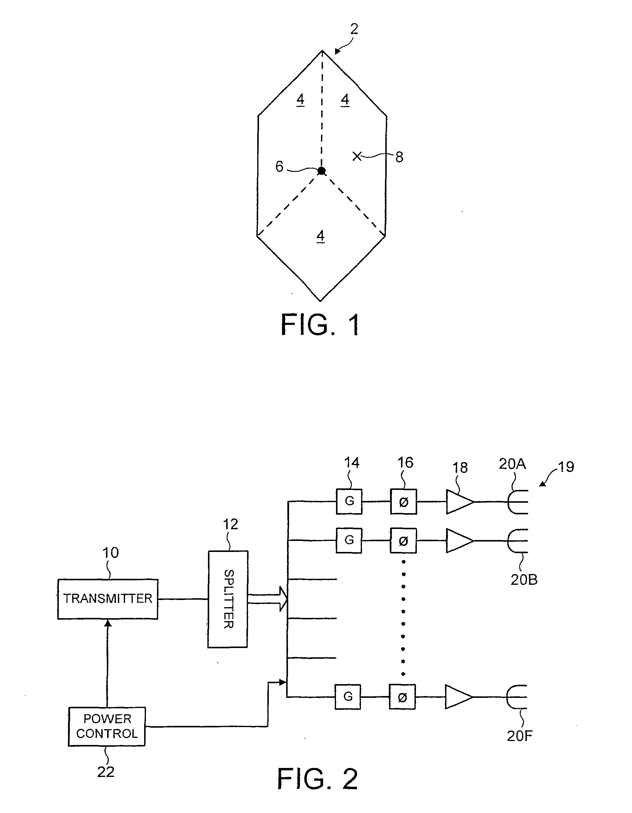
[0026] Reference is now made to FIG. 1 which shows part of a cellular telecommunications network 2 in which embodiments of the present invention can be implemented. The area covered by the network is divided into a plurality of cells, three of which are shown in FIG. 1. Each cell 4 has associated therewith a base transceiver station 6. In the example shown in FIG. 1, the base transceiver station associated with each cell 4 is provided at a common location. The base transceiver stations 6 are arranged to communicate with mobile terminals 8 located in the cell 4 associated with a given base station.

[0027] The embodiment of the present invention will be described in the context of a GSM system. It should be appreciated however that embodiments of the present invention can be used with any other system such as other frequency division multiple access systems, time division multiple access systems and spread spectrum systems such as code division multiple access. Embodiments of the prese...


PUM


Abstract

An antenna system for a transmitter comprising an array of antennas and control means. The antennas are arranged to transmit over all or part of the transmitters coverage area The control means control the number of antennas that are used to transmit a signal in dependence on the width of the signal to be transmitted.

Description

[0001] The present invention relates to an antenna system and in particular but not exclusively to an antenna system for use in a base transceiver station of a wireless telecommunications network.BACKGROUND TO THE INVENTION[0002] An area covered by a cellular telecommunications network is divided into a plurality of cells. Each of these cells has a base station arranged to transmit signals to and receive signals from mobile stations located in the cell associated with the respective base station. Mobile stations will be in active communication with the base station associated with the cell in which the mobile station is located.[0003] In order to improve the capacity and / or the signal to interference ratio, beam steering or beam selection techniques have been proposed. With beam steering or selection techniques, a base station is able to generate one or more beams. In the case of beam selection, the base station will be capable of producing a fixed number of beams to cover the cell ...

Claims


Application Information

Patent Timeline
Patent Type & Authority Applications(United States)
IPC IPC(8): H01Q3/24H01Q3/26H04B7/06
CPCH01Q3/24H04B7/0613H01Q3/26
Inventor SHURVINTON, BILLHANCOCK, CHRIS
Owner NOKIA SOLUTIONS & NETWORKS OY
Why Eureka
Try Eureka